74
1. Disconnect the platform measuring voltage lines from the terminal strip
(pins 3 and 4) in the A/D converter. Then short circuit these two lines and
connect them to pin 7 (GND) of the terminal connector. If the A/D converter is
intact, the weight readout should be stable.
Disconnect the cable from the platform.
2. Connect the strain-gauge simulator and turn the switch to simulate different
input signals. The weight readout should be stable.
Replacing the Digital PCB
Note: If communcation problems occur during communication with connected devices
(such as a printer), check the cable connections and the data transfer parameters
first; if the error source is not found, start the internal test program.
– Turn off the indicator.
– Press and hold the k key and turn the indicator on again. The test program
starts.
In case of defect, replace the digital PCB.
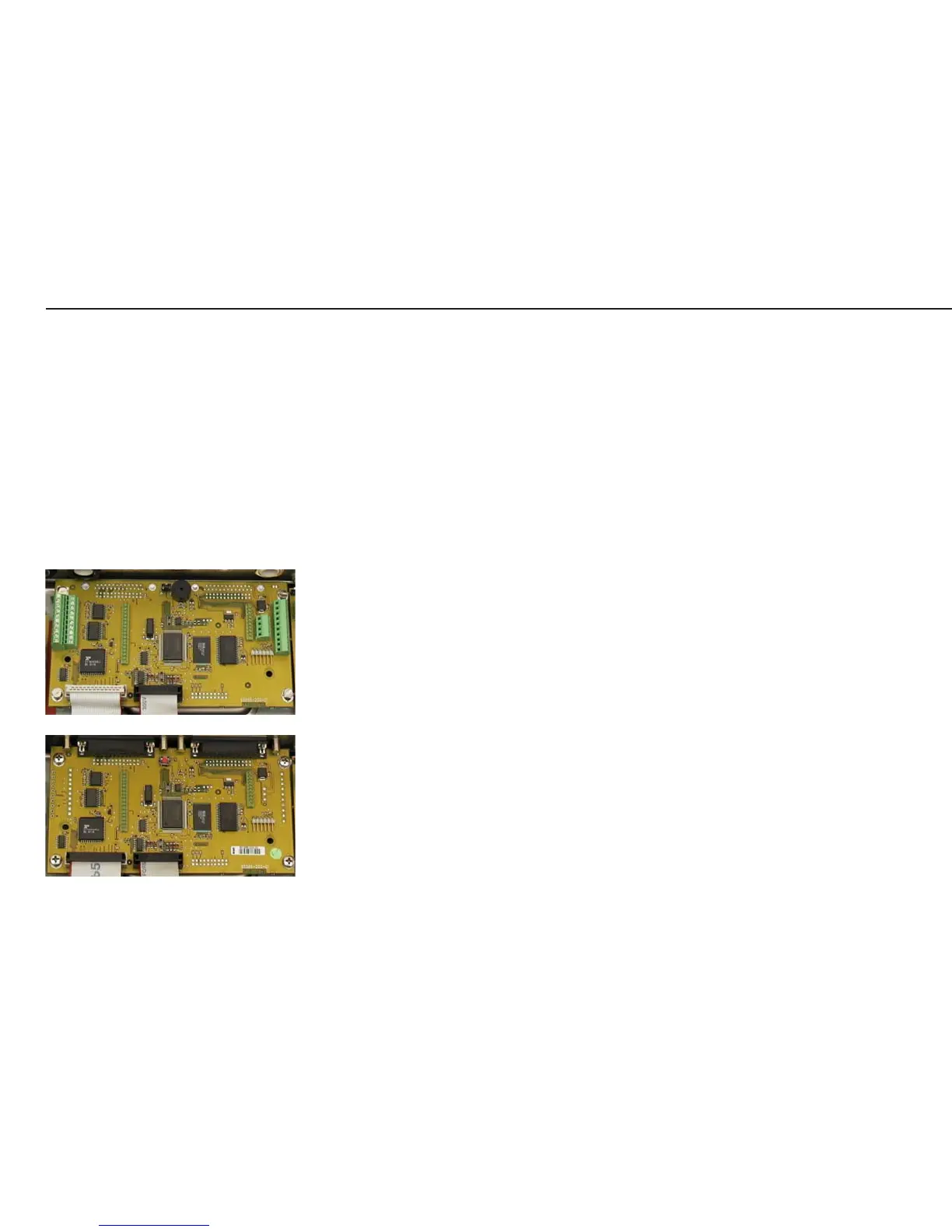
Some Combics indicators are equipped with D-Sub 25 female connectors, and
some with cable glands; make sure you order the correct PCB for your indicator
(see the illustration on the left).
– After replacing the digital PCB, use the PPLoader program to load the
application software, if necessary.
– Afterwards, enter the model designation and the Serial number of the Combics
scale (see pages 65 and 67).
haupt_pg.jpg
or
haupt_25.jpg