78
Off-center Load Adjustment: 0-ohm Resistors (Example)
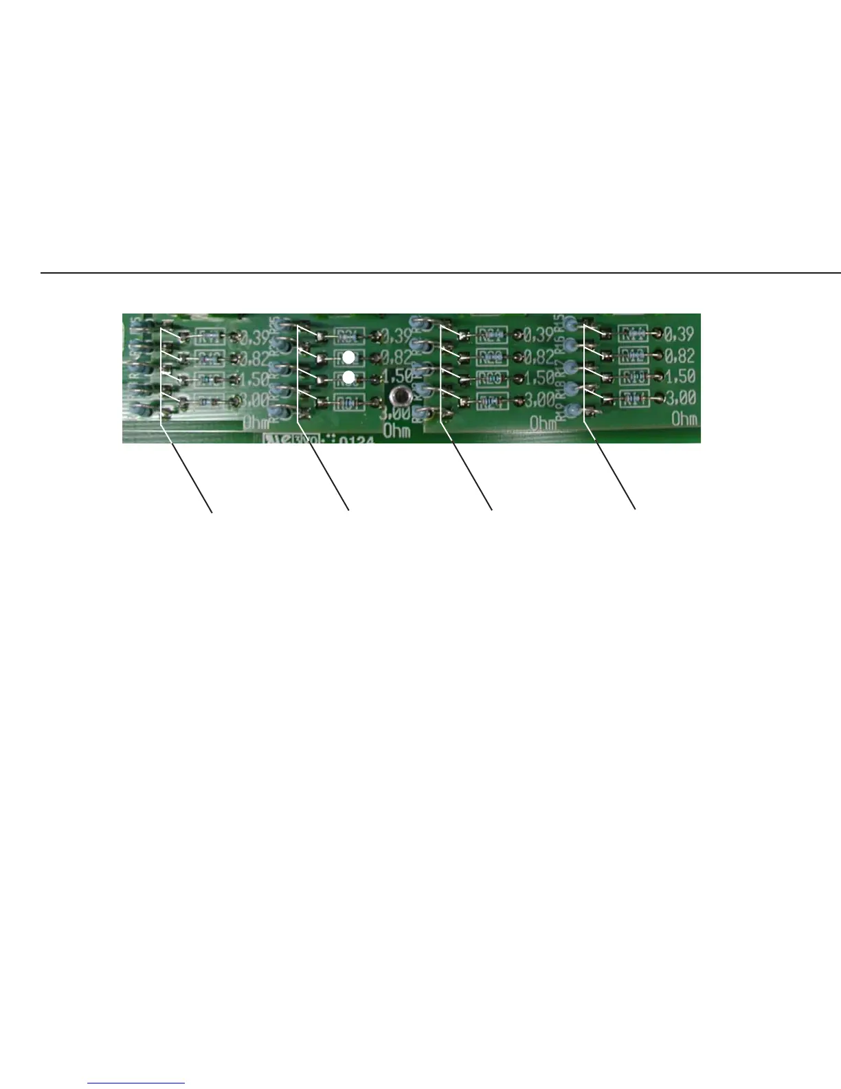
In the example given on page 75, the two 0-ohm resistors (marked by a white dot) must be removed. This activates the
adjustment resistors (0.82 and 1.5 ohms).
Follow the same procedure to determine the resistance values for load cells 1 and 2, and remove the 0-ohm resistors if
necessary.
The allocation of load cells in the weighing platform to contact on the adjustment PCB can be determined by checking
the wiring in the weighing platform.
Note: On stainless steel models, the IP67 protection must be checked after closing the
junction box.
eckl_4.jpg
0-ohm-resistors and
the corresponding ad-
justment resistors of
load cell no 4
0-ohm-resistors and
the corresponding ad-
justment resistors of
load cell no 3
0-ohm-resistors and
the corresponding ad-
justment resistors of
load cell no 2
0-ohm-resistors and
the corresponding ad-
justment resistors of
load cell no 1