Pin Assignment Chart
Models CAISL1 and CAISL2 (IP44 protection)
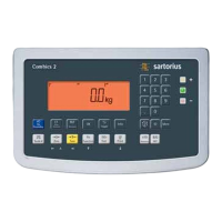
COM1 female connectors:
25-pin D-Submini female connector (DB25S) with screw lock hardware for cable
gland
Recommended interface connector:
25-pin D-Submini (DB25) with shielded cable clamp assembly and shield plate
(Amp type 826 985-1C) and fastening screws (Amp type 164868-1)
COM1 pin assignments
Pin 1: Shield
Pin 2: Data output (TxD)
Pin 3: Data input (RxD)
Pin 4: GND
Pin 5: Clear to send (CTS)
Pin 6: Not assigned
Pin 7: Internal ground (GND)
Pin 8: Internal ground (GND)
Pin 9: Not assigned
Pin 10: Not assigned
Pin 11: +12V for printer
Pin 12: RES_OUT\
Pin 13: +5V Switch
Pin 14: Internal ground (GND)
Pin 15: Universal switch
Pin 16: Control output: “lighter"
Pin 17: Control output: “equal"
Pin 18: Control output: “heavier"
Pin 19: Control output: “set”
Pin 20: Data terminal ready (DTR)
Pin 21: Ground power supply (GND)
Pin 22: Not assigned
Pin 23: Not assigned
Pin 24: Power supply +15 to 25V (peripherals)
Pin 25: +5V
3
1
4
2
6
5
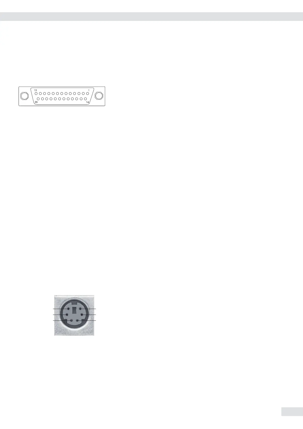
PS/2 socket pin assignment on Combics 2
Pin 1: Keyboard data (data interface cable)
Pin 2: Not assigned
Pin 3: GND (ground)
Pin 4: 5V switched
Pin 5: Keyboard clock
Pin 6: Not assigned
Connecting an IS Weighing Platform to a Combics 2
You can connect an IS weighing platform to WP2.
Features – IS weighing platforms process weighing data independently of the indicator.
– Internal calibration/adjustment option
– IS...-0CE models: have a separate approval number, printed on a tag that is
affixed to the cable.
– Please observe the conditions described in the manual for the weighing
platform you connect.
Operating Instructions Combics Indicators 13
Getting Started