Do you have a question about the Sartorius Combics 2 CAIXS2 and is the answer not in the manual?
Explains symbols and their meanings used throughout the manual for understanding conventions.
Describes how menu settings are presented for orientation and language selection.
Details the IP rating and conditions for maintaining it, ensuring protection against environmental factors.
Defines the intended industrial use of the indicator and its suitability for explosive atmospheres.
Identifies connections and features on the rear panel of the indicator for connectivity.
Specifies conditions to avoid during storage and shipping to maintain equipment safety.
Lists environmental factors to avoid at the installation site for optimal performance.
Procedure for allowing the device to adjust to ambient temperature to prevent condensation.
Details the process of connecting an intrinsically safe analog Sartorius platform for operation.
Instructions for installing cables, emphasizing caution with the cable gland for IP rating.
Specifies requirements for connecting a Class 1 device to a grounded outlet for electrical safety.
Safety measures for connecting to outlets without a protective grounding conductor.
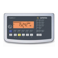
Identifies and describes the display elements and keypad functions of the indicator for user interaction.
Provides an example of how to change the device's display and printout language for user interface customization.
Explains the purpose and activation of Service mode for accessing additional setup and calibration functions.
Explains settings like standard/verifiable configuration, range selection, and scale interval for scale definition.
Covers minimum load, available weight units, and calibration/adjustment unit settings for scale configuration.
Explains when and how geographical data can be entered and its precedence for accuracy.
Lists menu parameters related to adjusting the scale without using external weights.
Details the basic weighing features and operations, including zeroing, taring, and unit toggling.
Explains the automatic taring function based on minimum load detection for efficient weighing.
Describes how to set the minimum load threshold for automatic taring and printing.
Details settings for display lighting, including on, off, and timer options for user interface.
Details how to open the menu access switch located on the back of the indicator to enable calibration.
Instructions on how to turn on the SQmin display and configure printout options for quality control.
Specifies the menu path and factory settings for ID code names for data tracking.
Provides an overview of available applications and functions, indicating their usage and capabilities.
Explains how to enter the average piece weight, a crucial step for accurate piece counting.
Explains how to set the minimum load required to initialize the Counting application for proper start.
Describes using two platforms of the same type for counting different materials with flexibility.
Explains using one high-resolution platform as a reference for weighing heavier samples efficiently.
Explains the importance of the reference weight and methods to enter it for accurate measurements.
Explains how to set the minimum load required to initialize the Neutral Measurement application.
Explains how to enter the number of sub-weighing operations for calculating averages.
Describes the three methods to start the averaging routine: manual, manual with user-defined, and automatic.
Explains methods to enter the reference percentage value required for accurate percentage calculations.
Explains how to set the minimum load required to initialize the Weighing in Percent application.
Lists features of Checkweighing, including setting target values, tolerance limits, and display modes.
Details the tare function within the Checkweighing application for accurate results.
Specifies the menu path to open for Checkweighing application preparation.
Lists features of Classification, including the number of classes and how limits are entered.
Explains how to enter class delimiters by saving weight values or percentages for sorting.
Lists parameters for Classification, including minimum load and quantity settings for configuration.
Lists features of Totalizing, including weighing items, saving values, and automatic printout for accumulation.
Explains how to configure printouts for totalizing data, including manual and automatic printing.
Lists features of Net Total Formulation, including weighing components and display modes for recipes.
Explains how to configure printouts for net total formulation, including component records.
Illustrates combining Counting, Checkweighing, and Totalizing applications for portioning workflows.
Details how to supplement printouts with GMP headers and footers for compliance in regulated environments.
Describes how to save product data, using the Counting application as an example for data management.
How to display information for a single product or tare value stored in memory for data retrieval.
How to browse and view information for all memories containing product or tare data for data overview.
Provides technical specifications for serial interfaces (RS-232, RS-485, RS-422), transmission rates, and protocols.
Details the SBI interface and its data output configuration options for specific communication protocols.
Explains the format of error messages, including position and error code numbers for troubleshooting.
Explains how to supplement printouts with GMP headers and footers for compliance in regulated environments.
Provides sample printouts for Weighing application, showing data blocks and IDs for understanding output.
Recommends regular servicing by Sartorius technicians for optimal performance and equipment longevity.
Safety precautions and instructions for performing repairs, emphasizing authorized personnel and spare parts.
Guidelines for cleaning the indicator, emphasizing compliance with hygienic standards and avoiding liquids.
Lists conditions under which safe operation is no longer ensured and actions to take for device safety.
Provides technical specifications for the ADC scale interface, including load cell connection and sensor technology.
Details the bidirectional intrinsically safe RS-232, RS-422, and RS-485 interfaces for communication.
Details AC adapters and external battery options for powering the indicator, including ATEX/FM approved models.
Describes the installation service package offered by Sartorius in Germany, including training.
Outlines the main menu categories (APPLIC, FN-KEY, SETUP, INFO, LANGUAG, ADC.CON) and their sub-menus.
Details menu parameters for applications like Counting, including minimum load and resolution settings.
Lists menu parameters for Neutral Measurement and Animal Weighing (Averaging) applications.
Details menu parameters for Weighing in Percent, Checkweighing, and Classification applications.
Lists menu parameters for Net-Total, Totalizing, Automatic Taring, and Minimum Tare settings.
Details setup parameters for weighing platforms, serial interfaces, and ambient conditions for configuration.
Lists various calibration and adjustment options, including external, internal, and linearization procedures.
Resets all applications and settings to factory defaults for restoring original configurations.
Explains settings for SBI data protocols, including baud rate, parity, and handshake for communication.
Details printer configuration settings for different printer types (YDP20, YDP14IS, YDP04IS) for data output.
Settings for automatic shutoff of display and control unit via timer or manual selection for power management.
Explains settings for ISO/GMP compliant printouts, including activation and timing for quality assurance.
Allows selection of language for display, calibration, and GMP-compliant printouts for user interface customization.
Details ADC configuration settings, including ranges, scale interval, maximum load, and weight units.
Diagrams illustrating external connections for power supply and weighing platforms using various options and interfaces.
Diagrams showing connections for data adapter boards, RS232/RS485/RS422 interfaces, and optional modules.
Details optional cables for connecting the YDI05-Z interface converter to scales or PCs via RS-422 or RS-232.
Details the intrinsic safety parameters and connection method for analog weighing platforms.
Shows wiring for digital weighing platforms and RS232/RS485 parameters for intrinsic safety.
Shows wiring for digital I/O signals and connections to junction boxes and foot switches for intrinsic safety.
Details RS485 parameters and connections for interface converters and safety barriers for intrinsic safety.
Certificate of compliance for hazardous location electrical equipment according to Canadian requirements.
Important conditions for using the intrinsically safe indicator in hazardous environments for safe installation.
Continues electrical parameters for CAIXS2 (COM1) output and input/output for WP Board, including RS485 communication.
Lists the intrinsic safety ratings for Class I, II, III, Division 1, Groups A-G, Zone 1, Group IIC, and Zone 21, Group IIIC.
Lists approval standards and documents related to the equipment's certification for compliance.
Repeats intrinsic safety ratings for Class I, II, III, Division 1, Groups A-G, Zone 1, Group IIC, and Zone 21, Group IIIC.
Continues electrical parameters for CAIXS2 (COM1) output and input/output for WP Board, including RS485 communication.
Repeats intrinsic safety ratings for Class I, II, III, Division 1, Groups A-G, Zone 1, Group IIC, and Zone 21, Group IIIC.
Lists approval standards and documents related to the equipment's certification for compliance.
Lists the intrinsic safety ratings for Class I, II, III, Division 1, Groups A-G, Zone 1, Group IIC, and Zone 21, Group IIIC.
Contains supplementary information regarding electrical parameters for WP-Karte and COM1 connections.
Provides further details on electrical parameters for WP-Karte and COM1, including RS485 communication.
Introduces the purpose of the report and lists standards for compliance with regulations.
Lists relevant United States and Canadian standards for electrical equipment in hazardous locations.
Lists ATEX intrinsic safety ratings for Class I, Zone 1, Group IIC and Zone 21, Group IIIC hazardous locations.
Important conditions for using the intrinsically safe indicator in hazardous environments for safe installation.
Continues electrical parameters for CAIXS2 (COM1) output and input/output for WP Board, including RS485 communication.
Continues electrical parameters for CAIXS2 (COM1) output and input/output for WP Board, including RS485 communication.
Details electrical parameters for DC supply adapter cables for intrinsic safety.
Continues electrical parameters for CAIXS2 (COM1) output and input/output for WP Board, including RS485 communication.
Describes the CAIXS2 indicator's use for data handling and indication in weighing systems.
Details the examination and testing procedures conducted for US/Canadian and ATEX compliance.
Provides guidance on installations, tampering, certification systems, and compliance with electrical codes.
Details the manufacturer's responsibilities regarding documentation, testing, and disclosure of defects.
Summarizes that the apparatus meets FM Approvals requirements and relevant standards.
Provides equipment details and conditions of certification for the IECEx certificate.
Lists electrical parameters for DC supply adapter cable and data adapter board (COM1) for the IECEx certificate.
Continues electrical parameters for CAIXS2 (COM1) output and input/output for WP Board, including RS485 communication.
Explains how to access the Setup menu using the 'Code' password and provides general and service passwords.
| Brand | Sartorius |
|---|---|
| Model | Combics 2 CAIXS2 |
| Category | Touch Panel |
| Language | English |