The Display
There are two display modes:
– Display for weighing (weighing values and calculated values)
– Display in “Menu mode" (device settings)
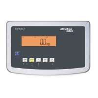
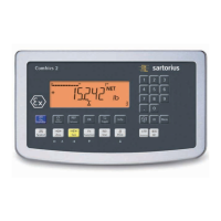
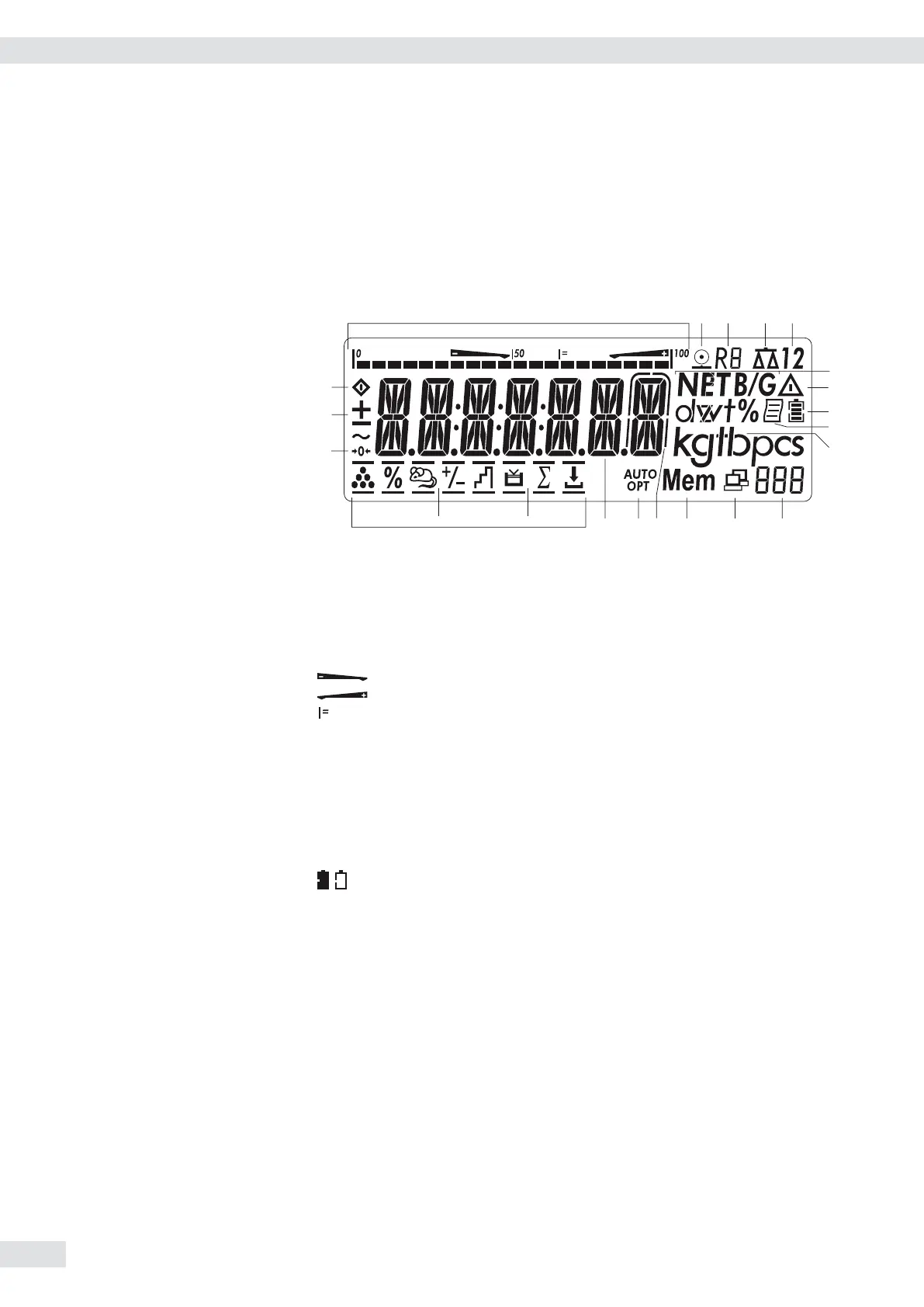
The figure shows the display of the Combics 2
Display in Weighing Mode
6
7
8
9
11
12131415
16
17
Appl. 1 Appl. 2 Appl. 3
1* Bar graph showing 10% intervals
– Shows the percentage of the weighing platform’s capacity that is “used
up” by the load on the scale (0% = lower limit, 100% = upper limit)
or
– Shows the measured value in relation to a target value (with the
“Checkweighing" or “Classification" applications)
Minimum for checkweighing
Maximum for checkweighing
Target value for checkweighing
2
S
Symbol for active print job
3 R8 Displays the active range on multiple-range scales
4 Indicates active weighing platform; flashes to prompt calibration/
adjustment
5* 1 2 Selected weighing platform 1 or 2
6 NET B/G Net/Gross value on the main display (with tare in memory or preset tare)
7
k
Identifies the value on the main display as calculated (value not valid in
legal metrology)
8
Battery charge status
9 p GMP-compliant printing in progress
10 Weight unit of the value displayed
11* Numeric display; e.g., showing the reference value
12* Symbol indicating data transfer
– Interface initialized (profibus/Ethernet)
– Flashes during data transfer (RS-232/485)
13* Mem Symbol for product data memory
14 In legal metrology, on equipment with e not equal to d, the digit
bordered for identification is not taken into account
15* AUTO/OPT
– AUTO: Depending on the weight value, a reaction is triggered in the
application
– OPT: Automatic optimization takes place for the Counting application
16 Measured value line: Weight value or calculated value
* = for Combics 2 only
34 Operating Instructions Combics Indicators
Operating Design