14
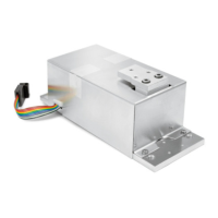
Replacing the Main PCB
– Before replacing the main PCB, try to read out the data from the main PCB
controller using the service software; if this is successful, you can load the
adjustment data in the controller of the new main PCB once it is installed. In
many cases, this precludes the need to adjust the weighing system.
Quick-test of the A/D Converter
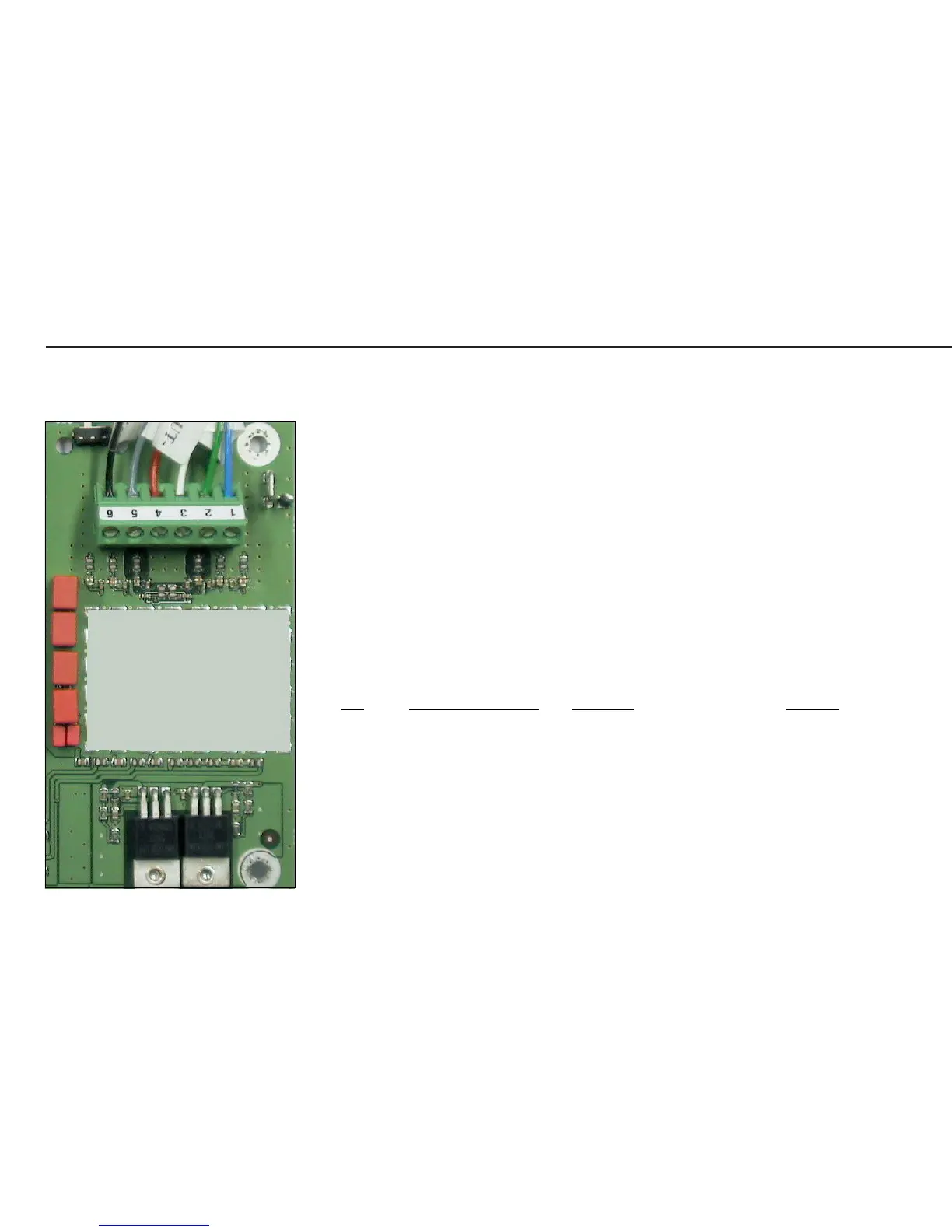
Pin Assignment Chart
No. Signal designation Meaning Voltage
1 BR_POS Bridge supply voltage (+) 4.5V ± 0.18V
2 SENSE_POS Sense (+)
Bridge supply voltage
3 OUT_POS Measuring voltage positive
4 OUT_NEG Measuring voltage negative
5 SENSE_NEG Sense (-)
Bridge supply voltage
6 BR_NEG Bridge supply voltage (-) –4.5V ± 0.23V
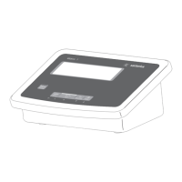
Repairing the Midrics Indicators
AUT23958_c.JPG