24
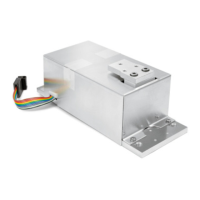
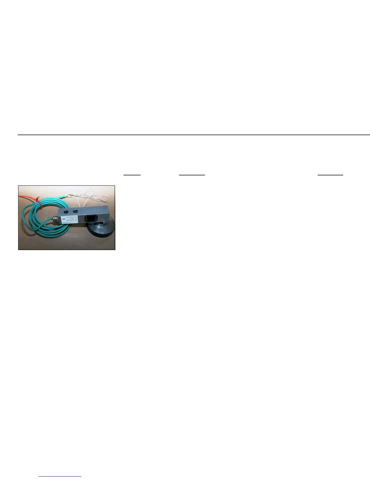
Cable from the Load Cell to the Junction Box (Terminals).
See below for the colors of the wires; the casing is gray.
Colors: Function: Terminal:
Ye (yellow) = Shield
Bl (blue) = BR_POS (Bridge supply voltage +) Supply +
Blk (black) = BR_NEG (Bridge supply voltage -) Supply -
Gn (green) = SENSE_POS (Sense +) Sense +
Gr (gray) = SENSE_NEG (Sense -) Sense -
Rd (red) = OUT_NEG (Measuring voltage negative) Signal -
Wh (white) = OUT_POS (Measuring voltage positive) Signal +
The terminal strip designations and the order of the terminals (1 - 4) are marked
on the PCB.
The sequence of the pin assignments of the terminals (1 - 4) should run from the
outside to the inside.
Adjusting the Weighing Platform
AUT24000.JPG