23
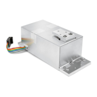
Cable from the Load Cell to the Junction Box 2 (Terminals)
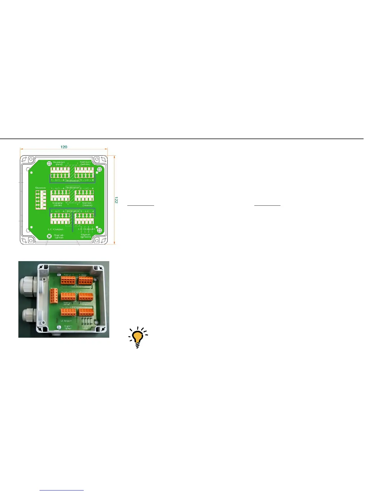
Color Coding
See page 33 for the colors of the wires; the casing is gray or black.
Function: Terminal:
Screen (Shield)
BBR_POS (Bridge supply voltage +) Supply +
BR_NEG (Bridge supply voltage -) Supply -
SENSE_POS (Sense +) Sense +
SENSE_NEG (Sense -) Sense -
OUT_POS (Measuring voltage positive) Signal +
OUT_NEG (Measuring voltage negative) Signal -
OUT_POS (Measuring voltage positive) Signal +
To connect the cable, the wires must be connected to the inner terminals (marked
in the illustration on page 20/22).
Note:
Note: The color coding of the connecting cable (A/D converter / indicator to
junction box) might be different when connecting a non-Sartorius
platform to the Midrics indicator.
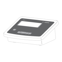
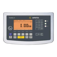
Adjusting the Weighing Platform
Kabel3.EPS
AUT23982.JPG