18
Digital I/O Interface
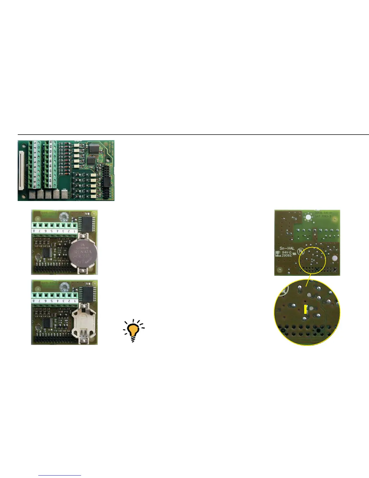
• For digital I/O interface pin assignments,
see page 16.
COM1 Interface With and Without
Clock Chip
• For COM1 variant pin assignments, see
page 16.
• The COM1 interface is required for
loading software.
• To enable loading of software, a solder
bridge must be closed on the back of the
COM1 interface (see illustration on the
right).
Note: Before commissioning the COM
ports, the PCBs (and any required
DIP switches) must be checked for
correct installation and settings.
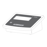
AUT23962.JPG
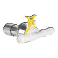
AUT23967.JPG
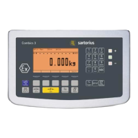
AUT23968.JPG
Repairing the Midrics Indicators
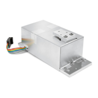
AUT23978.JPG
AUT23978a.JPG