21
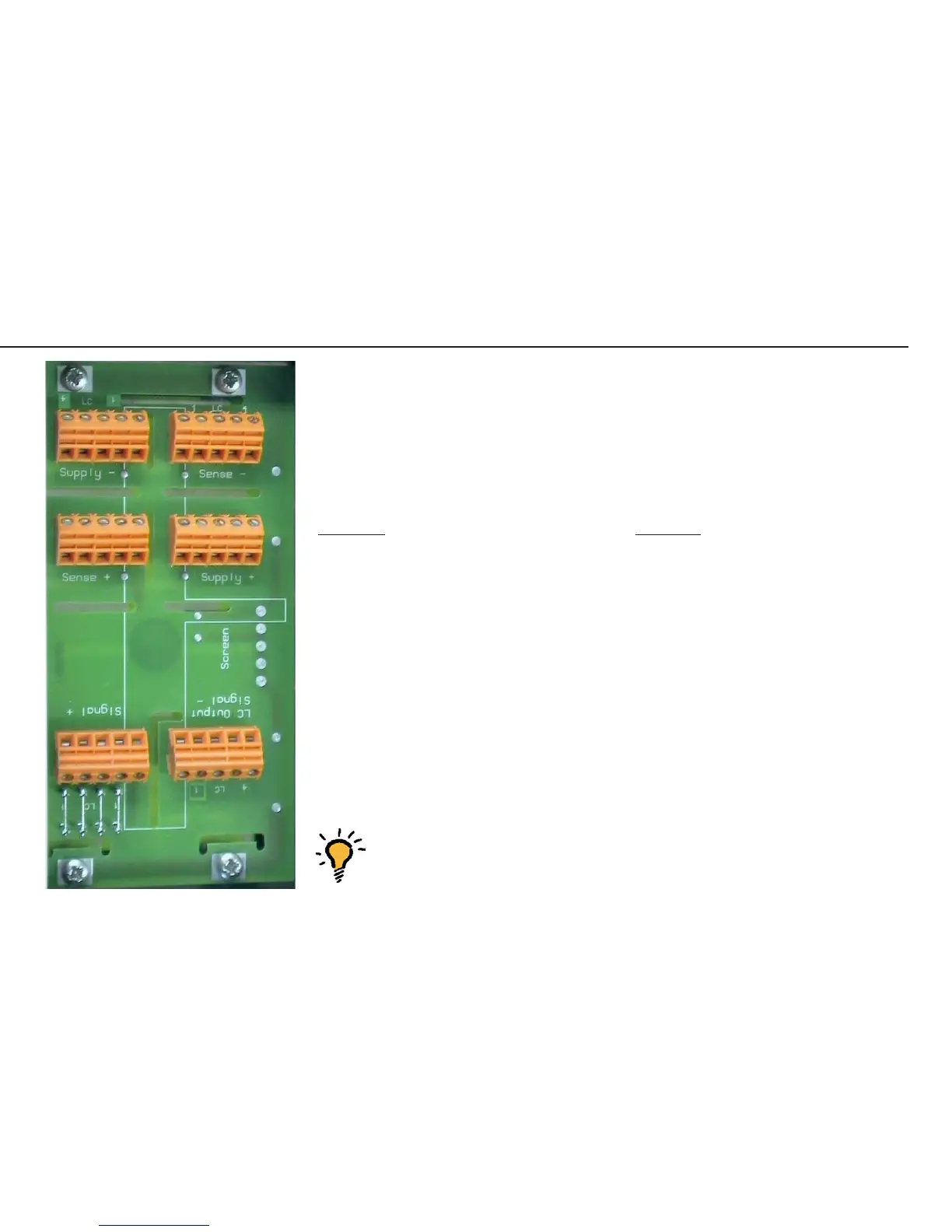
Pin Assignments in the Junction Box 1
Color Coding
Connecting cable 5.1 from the junction box (terminals) to the A/D converter/
indicator.
See page 33 for the colors of the wires; the casing is gray and black.
Function: Terminal:
Shield *
BBR_POS (Bridge supply voltage +) Supply +
BR_NEG (Bridge supply voltage -) Supply -
SENSE_POS (Sense +) Sense +
SENSE_NEG (Sense -) Sense -
OUT_POS (Measuring voltage positive) Signal +
OUT_NEG (Measuring voltage negative) Signal -
* The shield is connected to the housing by means of the cable gland (see page 29).
To connect the cable, the wires must be connected to the inner terminals (marked
in the illustration on page 19).
Note: The color coding of the connecting cable (A/D converter / indicator to
junction box) might be different when connecting a non-Sartorius
platform to the Midrics indicator.
Adjusting the Weighing Platform
Aut15158b.jpg
 Loading...