15
1. Connect the strain-gauge simulator and turn the switch to simulate different
input signals. The weight readout should be stable.
Replacing the Main PCB
Note: If communcation problems occur during communication with connected
devices (such as a printer), check the cable connections and the data
transfer parameters first; if the error source is not found, start the
internal test program.
– Switch off the indicator.
– Press and hold the k key while switching the indicator on again.
All segments are displayed.
– In case of defect, replace the main PCB.
– After replacing the main PCB, use the
PpLoadWH8.exePpLoadWH8.exe
PpLoadWH8.exePpLoadWH8.exe
PpLoadWH8.exe program to load the
software.
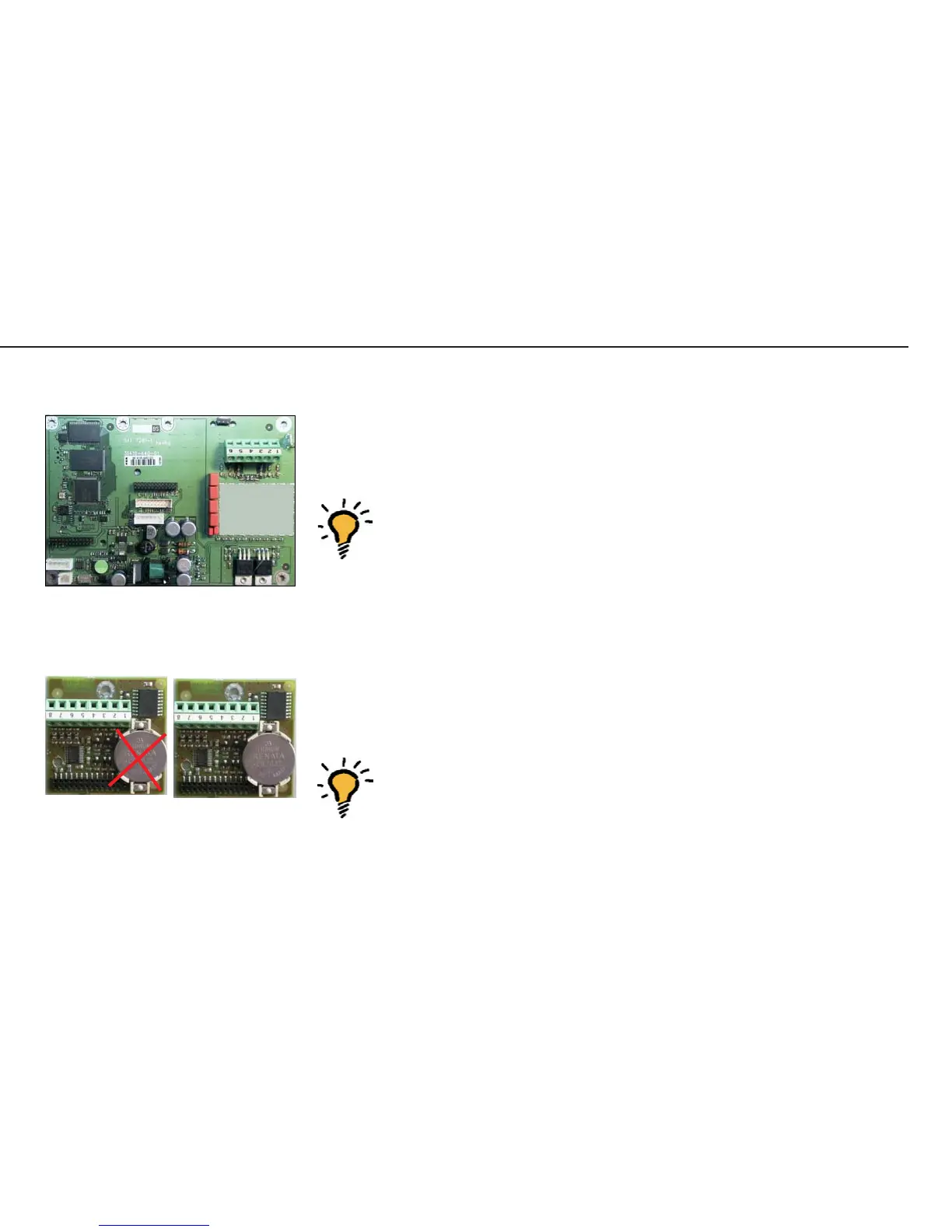
Note: To load the software, COM PCB model YDO01M-232 or YDO01M-232CLK
is required.
Following installation and commissioning of the new main PCB, the
display backlighting should blink on and off.
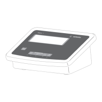
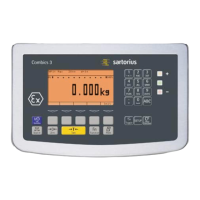
Repairing the Midrics Indicators
AUT23961_a.JPG
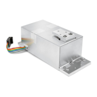
Main PCB
AUT23967.JPG
YDO01M-232 YDO01M-232CLK
without clock chip with clock chip