33
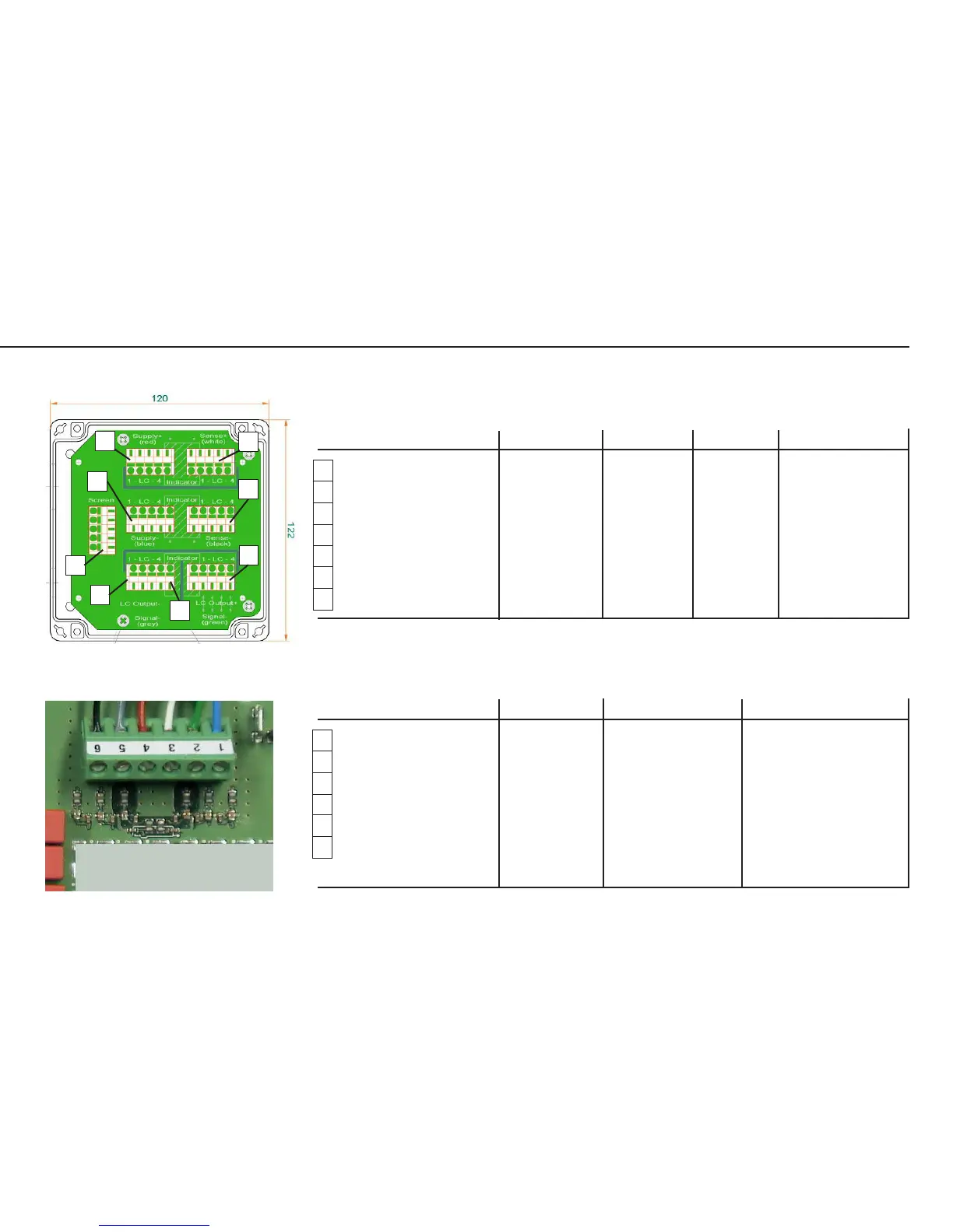
Wiring Diagram for the Load Cells (Junction Box 2)
Connections in the Junction Box for the Load Cells 1-4
Pin assignment Designation Variant 1
1)
Variant 2
2)
1 Supply v. pos. (in+) (V +) + Supply red blue
2 Supply v. neg. (in-) (V -) - Supply blue black
3 Test signal pos. (out+) Signal + + Output green white
4 Test signal neg. (out-) Signal - - Output gray red
5 Schirmleitung + Sense + + Sense white green
6 Schirmleitung - Sense - - Sense black gray
7 Shield GND screen gr. (Shield) (Shield)
1)
Sartorius Hamburg MP58T, green cable
2)
Midrics (011...), gray cable
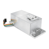
Connections in the Junction Box for the A/D Converter
Pin assignment Designation Variant 3
3)
Variant 4 com
4)
1 Supply v. pos. (in+) (V +) blue green
6 Supply v. neg. (in-) (V -) black / brown black
3 Test signal pos. (out+) Signal + white red
4 Test signal neg. (out-) Signal - red / pink white
2 Shield wire + Sense + green blue
5 Shield wire - Sense - gray brown
Shield GND (Shield) (Shield)
3)
MAPP4 / MAPS4...
4)
MAPS1... GF / IG
2
4
6
3
7
2a
Kabel3.EPS
1
5
A/D Converter
Repairing the Weighing Platforms
AUT24016_a.JPG