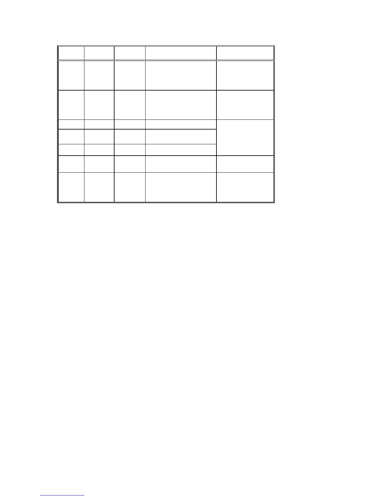
4
FIELD OFFSET
(BYTES)
LENGTH
(BYTES)
DESCRIPTION CONFIGURATION
27 136 6 Max. Demand 0NNNNN,
NNN.NN,
NNNN.N,
NNNNN.
28 142 6 Accumulated Max.
Demand
0NNNNN,
NNN.NN,
NNNN.N,
NNNNN.
29 148 5 Amp. Max. Demand L1
30 153 5 Amp. Max. Demand L2 0NNNN
NN.NN
31 158 5 Amp. Max. Demand L3
32 163 2 Contact Status
(Option B only)
HH
33 165 6 Returned Energy -0NNNN,
-NN.NN
-NNN.N
-NNNN.
Where:
N- 0, 1, 2, 3, 4, 5, 6, 7, 8, 9
S -
0 or "-"
T - 0, 1, or "-"
W - 0, 1, 2, 3, 4, 5, 6, 7, 8, 9 or "-"
H - 0, 1, 2, 3, 4, 5, 6, 7, 8, 9, A, B, C, D, E, F
NOTE
If a three wire configuration has been chosen the individual phase values for power factor, active
power, apparent power and reactive power will appear in the communication protocol as zeros
('0’s), because they have no meaning. Only the total three phase system values will be present.

 Loading...


