Chapter 3 Setup 25
3.14 Analog Output: A (optional)
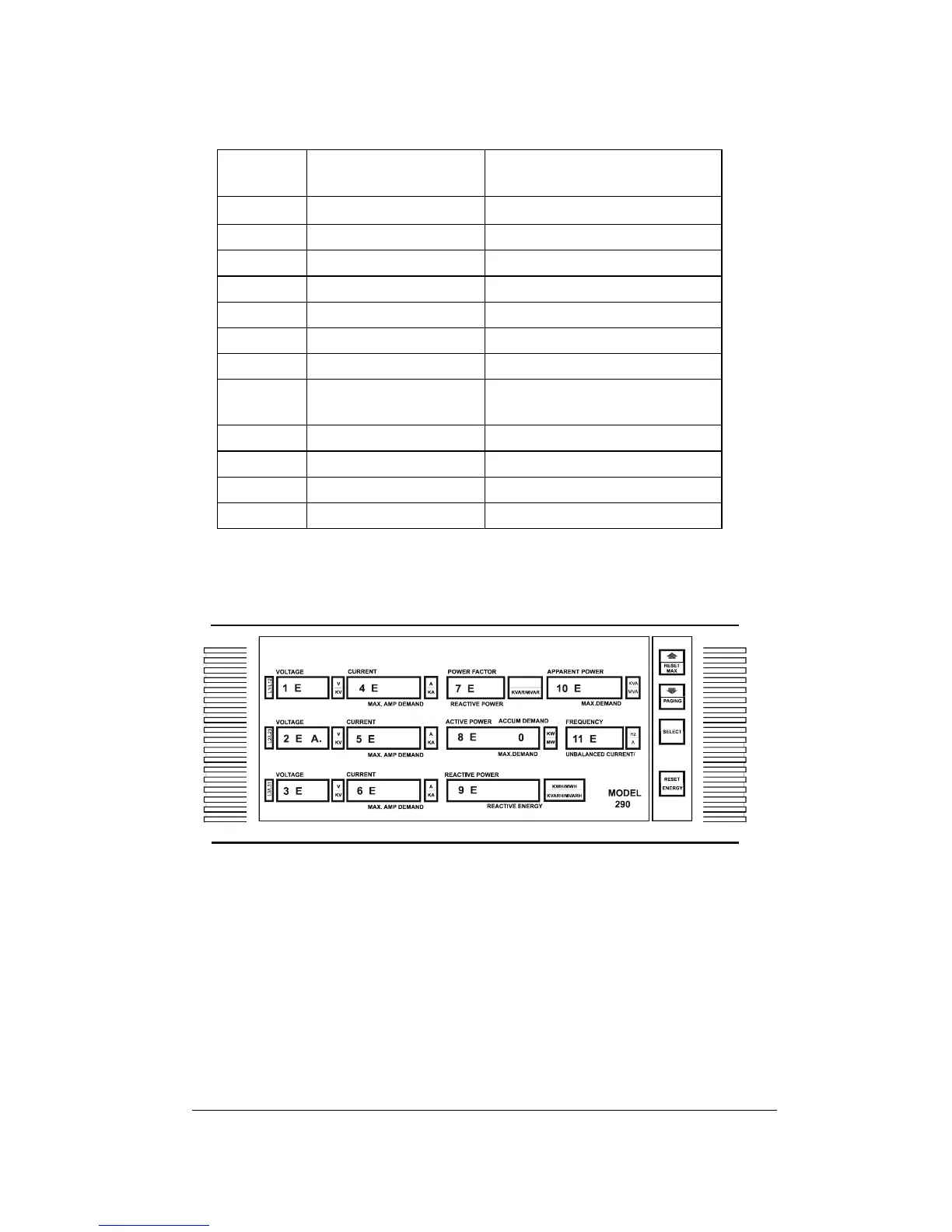
Up to 12 parameters may be assigned an analog output:
Windo
w
Parameter Name Description
1
U.1
Voltage L1 / L12
2
U.2
Voltage L2 / L23
3
U.3
Voltage L3 / L31
4
c.1
Current L1
5
c.2
Current L2
6
c.3
Current L3
7
PF
Power Factor
8 (right)
Ac.d
Active Power Accumulated
Demand
8 (left)
Ac.P
Active Power
9
rE.P
Reactive Power
10
AP.P
Apparent Power
11
Fr
Frequency
'A' is the overall code for Analog Output. A parameter allocated to
analog output is indicated by a number (e.g., '1 E' or '3 E') displayed in
that parameter's window. Where there is no allocation, a row of dots
will appear in the window.
- Use the ⇑ ⇓ keys to choose the parameter from the list above.
- Press SELECT; the dot will disappear from the 'A'.
- Use the ⇑ ⇓ keys to scroll to the appropriate values:
0 (internal analog output), or
1E - 12E (if 1 or 2 AX-8 analog expanders are connected).
- Press RESET; the dot will re-appear.
To cancel an allocation of a specific parameter to Analog Output, press
SELECT and then press the up and down arrows simultaneously. A
row of dots will appear in place of the number.