18 Chapter 3 Setup
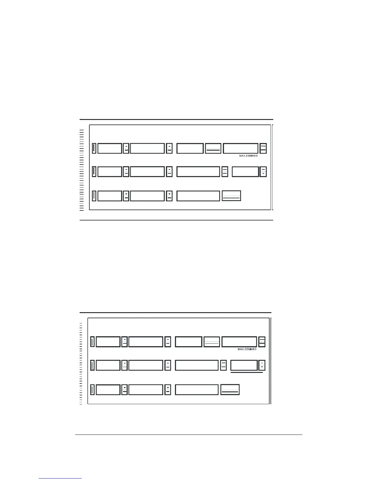
3.4 Current Transformer Primary Current: Ct
Notes: 1) Ct must be defined before relay setpoint definition.
2) For Option L, ground leakage primary current is
represented by Ct.G
This parameter defines the primary value of the Current Transformer.
- Press SELECT; the dot will disappear.
- Use the ⇑ ⇓ keys to scroll to the appropriate value (1 - 50000 A).
- Press RESET; the dot will re-appear.
UNBA LANCED CU RRENT/
APPARENT POWER
FREQUENCY
CURRENT
CURRENT
CURRENT
VOLTAGE
VOLTAGE
VOLTAGE
AC TIVE E NE RGY
MAX.D EM AND
REACTIVE POWER
POWER FACTOR
AC TIV E PO WE R
MODEL
1Ct.
MAX. AMP DEMAND
290
MAX. AMP DEMAND
MAX. AMP DEMAND
REACTIV E ENERGY
- Use the ⇑ key to move to the next setup parameter.
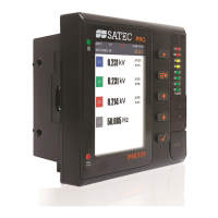
3.5 Power Demand Period: P
This parameter defines the time period over which average power
demand is calculated.
- Press SELECT; the dot will disappear.
- Use the ⇑ ⇓ keys to scroll to the appropriate value (1, 2, 5, 10, 15,
20, 30 or 60 minutes, or E for external synchronization).
- Press RESET; the dot will re-appear.
APPARENT POWER
FREQUENCY
CURRENT
CURRENT
CURRENT
VOLTAGE
VOLTAGE
VOLTAGE
AC TIVE E NE R GY
MAX.D EMAND
REACTIVE POWER
POWER FACTOR
AC TIV E PO WE R
MODEL
15P.
MA X . A MP D E MA N D
290
MA X . A MP D E MA N D
MA X . A MP D E MA N D
REACTIV E ENERGY
Use the ⇑ key to move to the next setup parameter.