ii
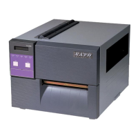
SATO CL608e/CL612e Service Manual
PN 9001079
Rev. B
Table of Contents
Section 4. Electrical Checks and Adjustments
5b Pitch Offset Adjustment .................................................................................. 4-9
6 Label Gap Adjustment ................................................................................... 4-10
7 Eye-Mark Adjustment ....................................................................................4-11
8 Feed/Backfeed Adjustment (Tear-Off).......................................................... 4-12
9 Feed/Backfeed Adjustment (Cutter) ............................................................. 4-13
10 Feed/Backfeed Adjustment (Dispenser) ...................................................... 4-14
11 Ribbon Sensor Verification ........................................................................... 4-15
12 Ribbon Sensor Adjustment (Near End)........................................................ 4-16
13 LCD Display Adjustment ............................................................................... 4-17
14 Print Darkness Adjustment ........................................................................... 4-18
Section 5. Mechanical Adjustments
1 Overview ........................................................................................................... 5-1
2 Ribbon Clutch Adjustments ............................................................................ 5-2
3 Print Head Position Adjustment ..................................................................... 5-5
4 Print Head Balance Adjustment...................................................................... 5-7
5 Ribbon Roller Adjustment ............................................................................... 5-8
6 Feed Roller Adjustment (Label Tracking)...................................................... 5-9
7 Timing Belt Tension Adjustment ................................................................... 5-11
8 Head Latch Adjustment................................................................................. 5-12
9 Notch/Gap Sensor Adjustment .................................................................... 5-13
Section 6. Replacement Procedures
1 Overview .......................................................................................................... 6-1
2 Replacing the Main Circuit Board .................................................................. 6-2
3 Replacing the Fuses........................................................................................ 6-7
4 Replacing the Power Supply ........................................................................... 6-9
5 Replacing the Stepper Motor ........................................................................ 6-12
6 Replacing the Timing Belts ........................................................................... 6-13
7 Replacing the Print Head............................................................................... 6-16
8 Replacing the Platen ...................................................................................... 6-19
9 Replacing the Ribbon Drive Clutch Washers .............................................. 6-23
10 Replacing the Ribbon Motion Sensor .......................................................... 6-27
11 Replacing the Paper End Switch (Micro-Switch) and the
Bottom Half of the Notch/Gap and Eye-Mark Sensors ............................... 6-30
12 Replacing the Top Half of the Notch/Gap Sensor ....................................... 6-34
13 Replacing the Display Panel or Keyboard ................................................... 6-37
Section 7. Factory Resets
1 Overview ........................................................................................................... 7-1
2 Factory/Service Test Print ............................................................................... 7-2
3 Clear Head Counters........................................................................................ 7-3
4 Clear Dispenser Counter ................................................................................. 7-4
5 Clear Cutter Counter ........................................................................................ 7-5
6 Clear EEPROM.................................................................................................. 7-6
7 Sample Test Prints ........................................................................................... 7-7
Section 8. Troubleshooting
1 Overview .......................................................................................................... 8-1
2 Initial Checklist ................................................................................................ 8-2
3 The IEEE 1284 Parallel Interface .................................................................... 8-2

 Loading...