Section 4: Accessories Installation
M84Pro Service Manual PN 9001111A Page 4-2
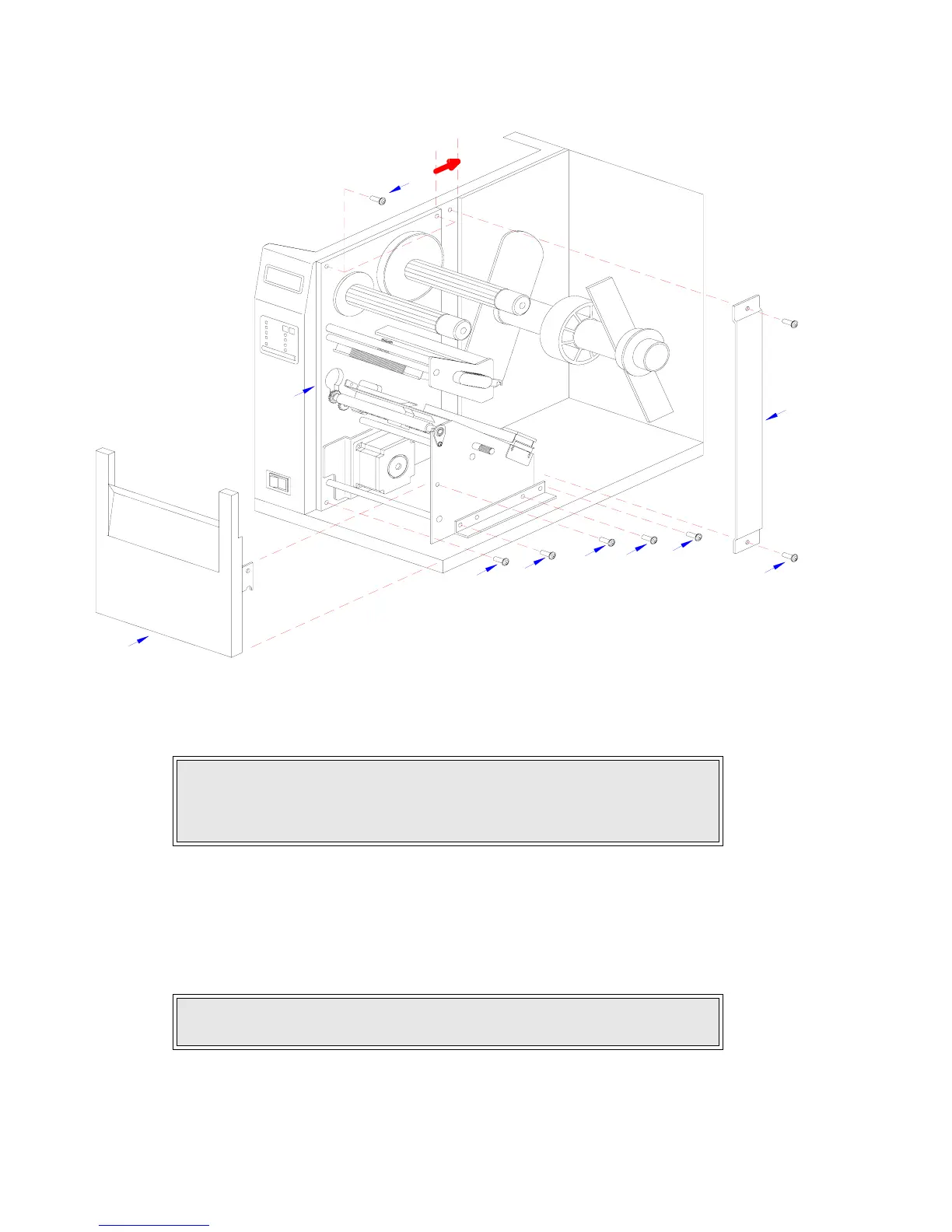
Figure 4-1a, Label Cutter Installation
7 Slide entire print mechanism fully toward the rear.
8 Reapply two screws (7) to side frame bracket (8) and four screws (5) to back panel (6) to
secure print mechanism.
9 Attach two hinge halves (9, Figure 4-1b) to the front base of the printer using two screws
(10) for each.
10 Install spacer panel (4) into the void left in front of print mechanism and secure using two
screws (3).
CAUTION: ENSURE WIRING HARNESSES ARE NOT PINCHED WHEN
ADJUSTING THE PRINT MECHANISM. THE PRINT MECHANISM WHEN
ADJUSTED, WILL COVER THE VOID LEFT BY THE REMOVAL OF THE
SPACER PANEL.
NOTE: Before tightening the hinge screws, pull the hinges forward to align
them.
4
5
6
5
2
7
1
7
5
3