Saia-Burgess Controls AG
Manual Manual PCD 1 / PCD 2 Series │ Document 26 / 737 EN22 │ 2013-11-26
4
Communication interfaces
4-43
MP-Bus PCD2.T500
Diagnostic LED
To the left of these keys are two LEDs (branch A on the left, branch B on the right)
which, in association with the keys, indicate the result of a completed diagnosis. If a
connected, addressed actuator does not communicate correctly with the Saia PCD
®
master station, the LED ashes. The number of ash signals matches the bus ad-
dress of the actuator. They are repeated 5 times, with interruption.
Function LED
These LEDs are visible even when the cover is closed and indicate the following
states:
LED off on
0 Channel 1 = Branch A
Channel 2 = Branch B
Channel 1 = Branch B
1 Branch A is switched on Branch A is switched off
2 Transmit signals at branch A
3 Transmit or receive signals at branch A
4 Branch B is switched on Branch B is switched off
5 Transmit signals at branch B
6 Transmit or receive signals at branch B
Base address
The PCD2.T500 Module can be slotted into any I / O module socket on the
PCD1 / PCD2. The base address of the socket is required for software linking in the
function boxes. For ease of wiring, it is recommended to choose a socket near to the
communications ports.
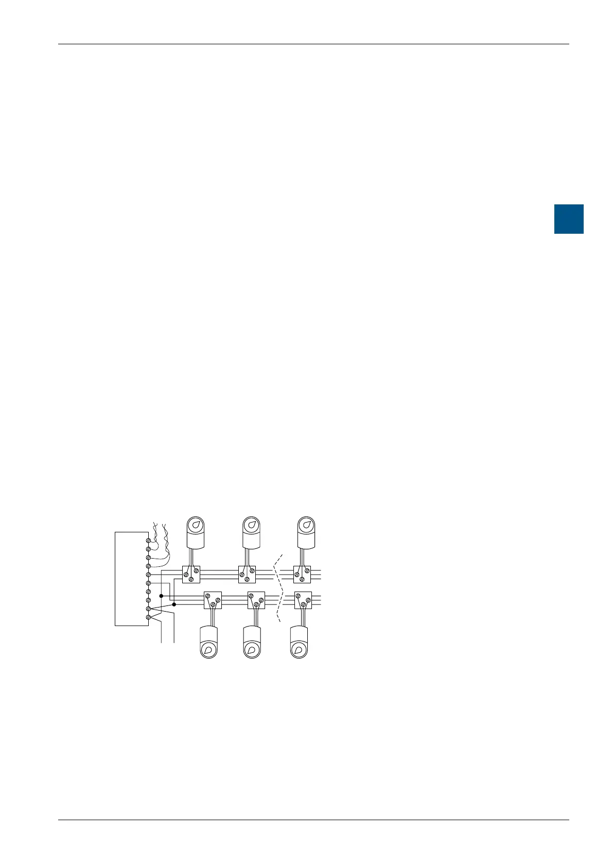
4.11.3 Connection and wiring
Branch B
Connecting boxes
Branch A
Communications channels
1 and 2
–
+
PP
BELIMO
8
–
+
PP
BELIMO
2
–
+
PP
BELIMO
1
–
+
PP
BELIMO
1
–
+
PP
BELIMO
2
–
+
PP
BELIMO
8
RX2
TX2
RX1
TX1
B COM
A COM
GND
GND
+24 VDC
GND
0
1
2
3
4
5
6
7
8
9
Terminal Designation Description
0 Rx2
Receive line Communications channel 2
1 Tx2
Transmit line Communications channel 2
2 Rx1
Receive line Communications channel 1
3 TX1
Transmit line Communications channel 1
4 B Com
Communication branch B
5 A Com
Communication branch A
6 -
Earth connection for actuators, branches A and B
7 -
Earth connection for actuators, actuators branches A and B