Saia-Burgess Controls AG
Manual Manual PCD 1 / PCD 2 Series │ Document 26 / 737 EN22 │ 2013-11-26
4
Communication interfaces
4-6
Onboard interfaces
4.5 Onboard interfaces
4.5.1 PGU connection (PORT # 0, PCD1 and PCD2) (RS-232) for connecting
programming devices
The PGU interface (Port # 0) is connected to a 9-pole D-Sub connector (female). The
interface is used to connect the programming device when the unit is commissioned.
The interface is of type RS-232c.
The pin conguration and associated signals are:
Pin Designation Meaning
1 DCD Data Carrier Detected The equipment signals to the computer that
it recognizes data on the line
2 RXD Receive Data Line for the receiving of data
3 TXD Transmit Data Line for outgoing (sent) data
4 n.c. Not Connected Not used
5 SGN Signal Ground Signal mass. Signal voltages are measured
against this line
6 DSR PGU Connected Recognition PGU. Attached equipment sig-
nals to the computer that it is operational, if
logical unity on this line lies close
7 RTS Request To Send Transmitters switch on. „send request“ (if
this line on logically unity stands, would like
to send the equipment data
8 CTS Clear To Send Ready-to-transmit-state. If this line stands
on logically “high”, the equipment can
receive data
9 +5 V Supply P100 Supply for the programming unit P100
The PGU protocol is provided for operation with a programming device. The use
of the PCD8.P800 service unit is supported from rmware version $301 for all
PCD1 / PCD2 controllers.
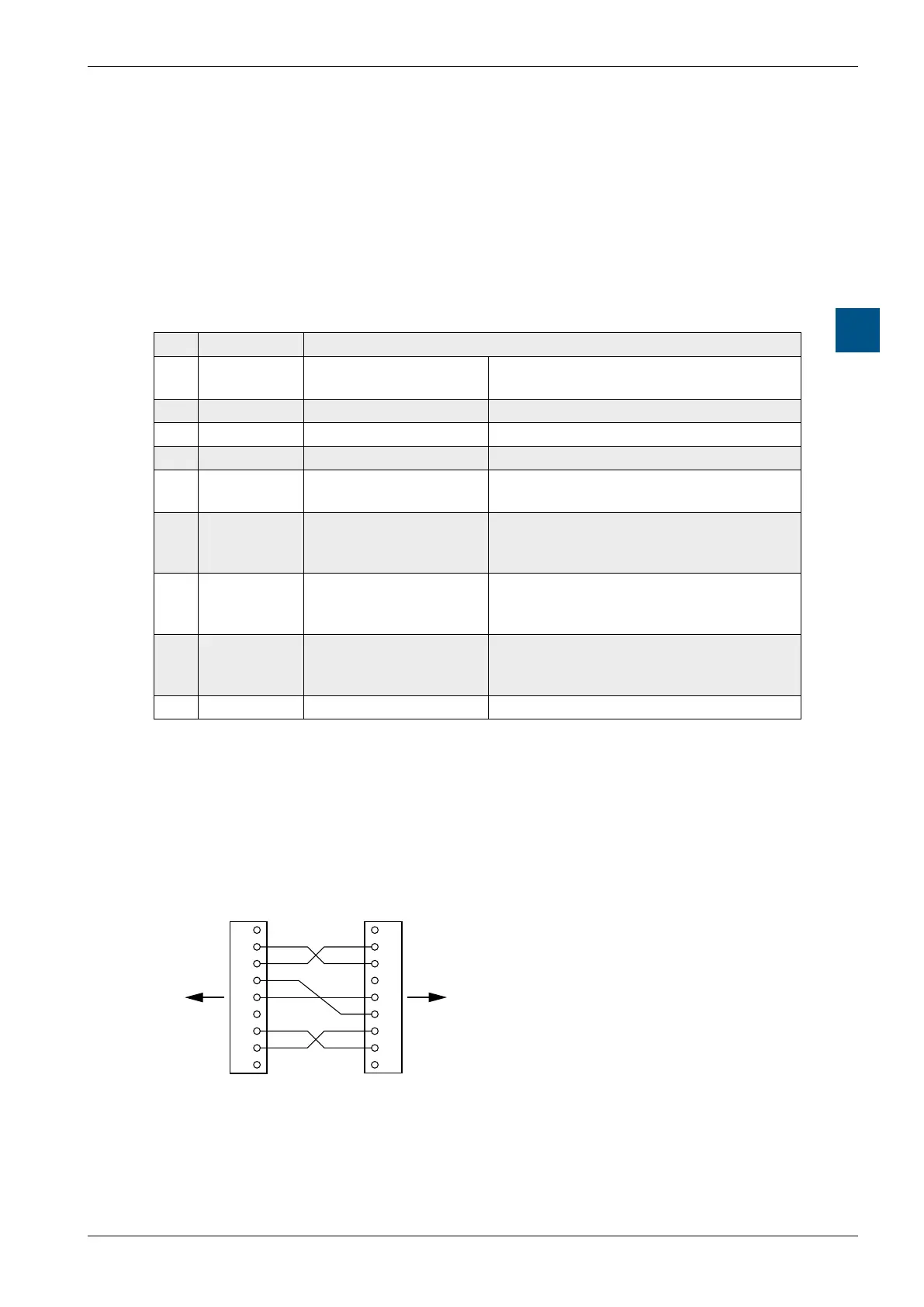
PCD8.K111 connecting cable
(P8 and S-Bus protocol, suitable for all PCD1 / PCD2 units)
2
1
4
3
6
5
8
7
9
2
1
4
3
6
5
8
7
9
SGN
DSR
SGN
TX
RX
RTS
CTS CTS
RTS
TX
RX
DTR
PC PCD
DCDDCD
D-SUB 9 pol.
(female)
D-SUB 9 pol.
(male)