Saia-Burgess Controls AG
Manual Manual PCD 1 / PCD 2 Series │ Document 26 / 737 EN22 │ 2013-11-26
4
Communication interfaces
4-7
Onboard interfaces
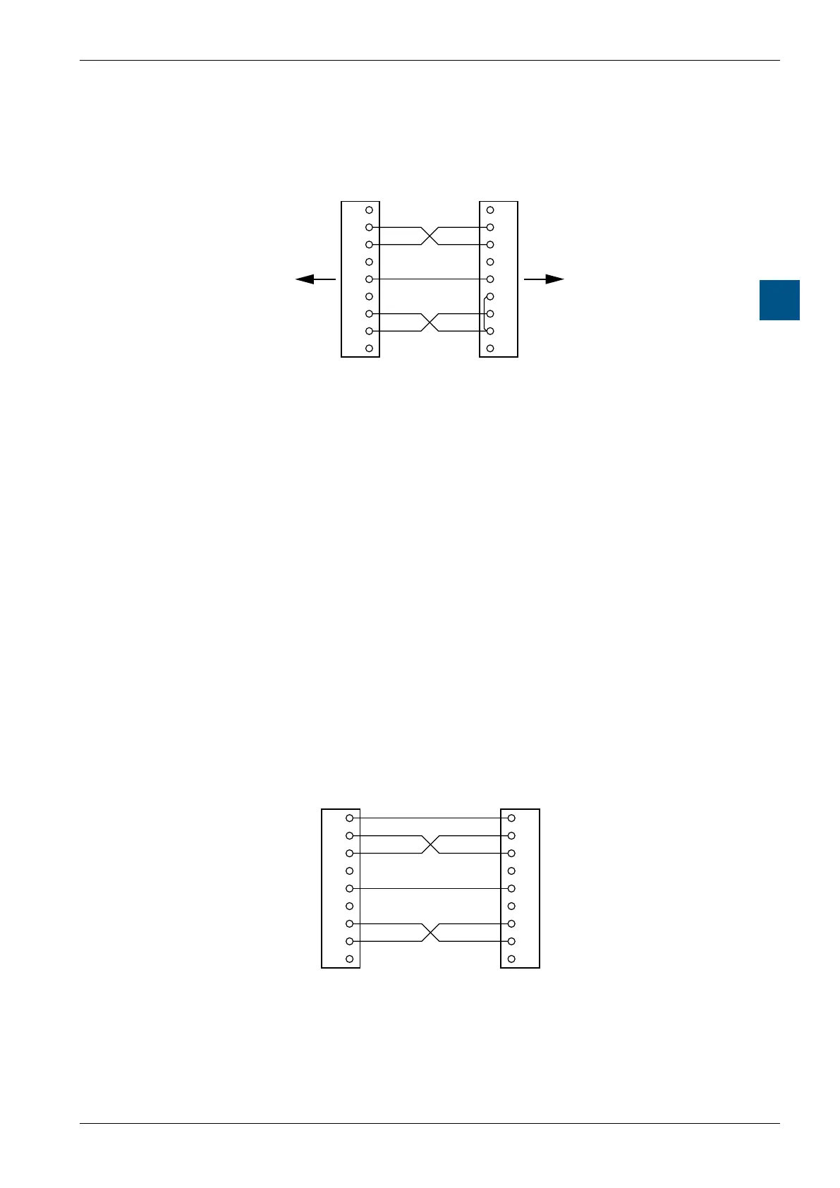
PCD8.K110 connection cable (obsolete)
(P8 protocol, suitable for PCD1.M110 / 120 and PCD2.M110 / 120 only)
SGN SGN
TX
RX
RTS
CTS CTS
RTS
TX
RX
2
1
4
3
6
5
8
7
9
2
1
4
3
6
5
8
7
9
DSR
D-SUB pol.
(female)
D-SUB 9 pol.
(male)
PC PLC
4.5.2 PGU connection (PORT # 0, PCD1 and PCD2) (RS-232)
as communication interface
When comissioning / programming are complete, the port can be used for other pur-
poses.
Option 1: Conguration with desired protocol
(S-Bus PGU conguration)
Option 2: Assignment (SASI) in the user program
(the port must not be congured as an S-Bus PGU port)
■ If another programming device is connected during operation
instead of the peripheral device, the unit will switch over
automatically to PGU mode (pin 6 logical “1” (DSR); in PGU
mode: DSR PING = “1”).
■ Before using the port to connect another peripheral device,
Port #0 must be recongured by means of an SASI instruction.
2
1
4
3
6
5
8
7
9
GND SGN
TX
RX
RTS
1)
CTS
1)
CTS
RTS
TXD
RXD
DCD PGD
PGU-Plug
D-SUB 9 pol.
(female)
PeripheralCable
+5V
(
just for PGU)
1) When communicating with terminals, check whether some connections are pro-
vided with bridges or need to be set to “H” or “L” with the “SOCL” instruction. It is
generally recommended to use a handshake (RTS / CTS)