Saia-Burgess Controls AG
Manual Manual PCD 1 / PCD 2 Series │ Document 26 / 737 EN22 │ 2013-11-26
5
Input/output (I/O) modules
5-22
Digital output modules
5.4.1 PCD2.A300, 6 digital outputs for 2 A each
Application
Low cost output module with 6 transistor outputs 5 mA … 2 A, without short-circuit
protection. The individual circuits are electrically connected; the voltage range is
10 … 32 VDC.
Technical data
Number of outputs: 6, electrically connected
Output current: 5 mA … 2 A (leakage current max. 0.1 mA)
Total current per module: 6 × 2 A = 12 A (on 100 % duty cycle)
Operating mode: Source operation (positive switching)
Voltage range: 10 … 32 VDC, smoothed
10 … 25 VDC, pulsed
Voltage drop: 0.2 V at 2 A
Output delay: Switch-on delay <1 µs
Switch-off delay <200 µs
with inductive loads the delay is longer, because of the
protective diode.
Isolation voltage: 1000 VAC, 1 min
Resistance to interference:
acc. to IEC 801-4
4 kV under direct coupling
2 kV under capacitive coupling (whole trunk group)
Internal current consumption:
(from +5 V bus)
1 … 20 mA
typically 12 mA
Internal current consumption:
(from V+ bus)
0 mA
External current consumption: Load current
Terminals: Pluggable 10-pole screw terminal block
(4 405 4847 0), for wires up to 1.5 mm²
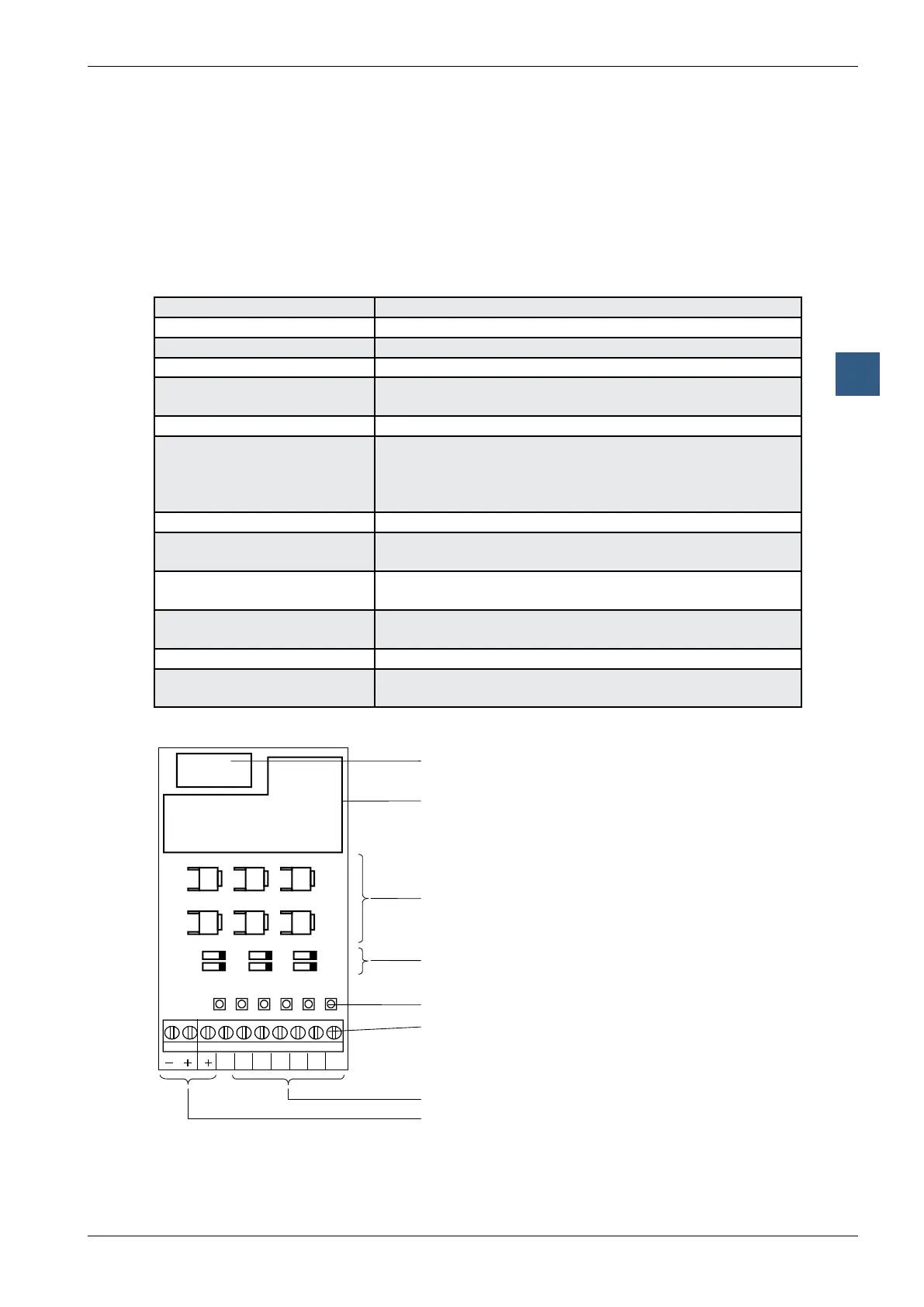
LEDs and connection terminals
Bus connector
Bus interface
Output transistors
(MOSFET)
Protective diodes
LEDs
Screw terminals
Outputs
Load supply
9 8 7 6 5 4 3 2 1 0
A0A1A2A3A4A5
A5 A3 A1
A4 A2 A0