Saia-Burgess Controls AG
Manual Manual PCD 1 / PCD 2 Series │ Document 26 / 737 EN22 │ 2013-11-26
5
Input/output (I/O) modules
5-115
SSI interface modules
5.17.1 PCD2.H150, SSI interface module for absolute encoder
Application
The PCD2.H150 Module is an interface module for the SSI standard. (SSI =
Synchronous Serial Interface). The SSI standard is used with most absolute
encoders. Details of SSI specications can be obtained from the STEGMANN
company’s brochure: “SSI-Technical Information”.
The hardware consists of an RS-422 port for the SSI interface and 4 general-purpose
digital outputs. Functionality is provided by an FPGA (eld programmable gate array).
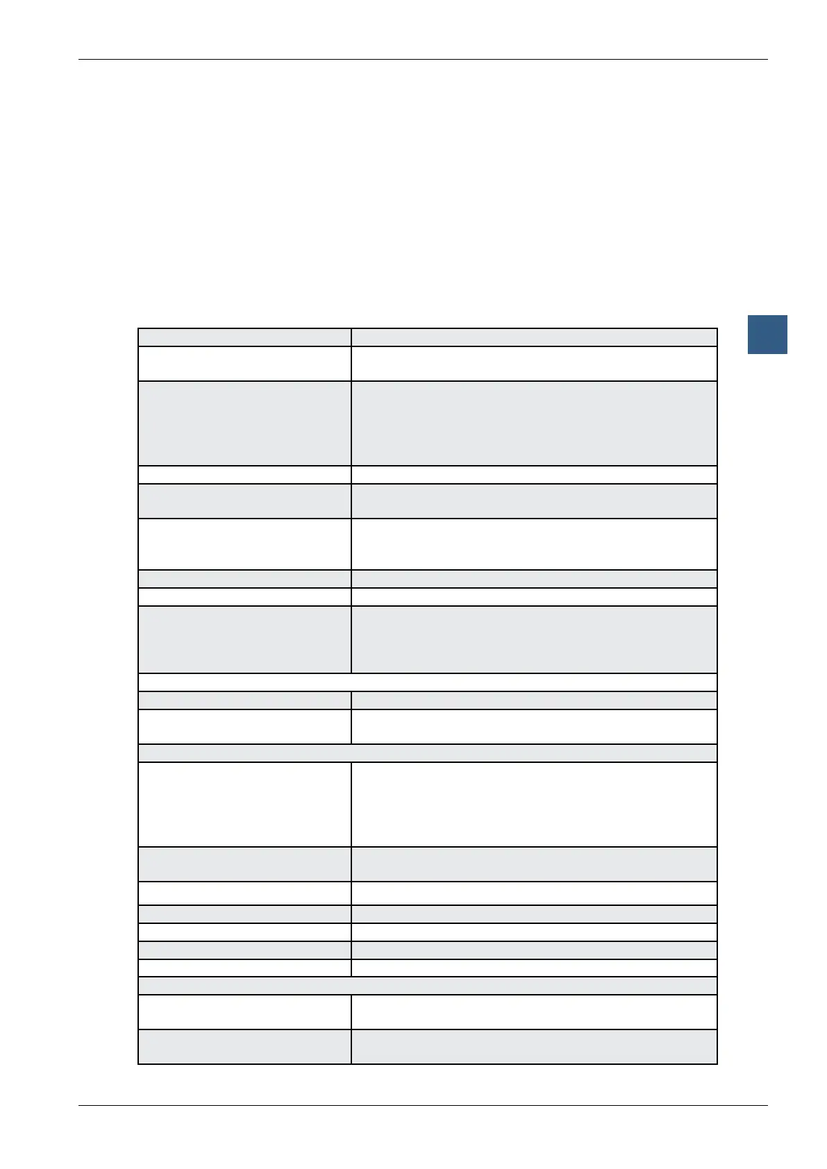
Technical data
Resolution: congurable for 8 … 29 data bits and 0 … 2 control bits
Clock frequency: congurable for 100 kHz, 200 kHz, 300 kHz
and 500 kHz (input lter designed for 500 kHz)
Frequency has to be selected
depending on cable length:
Cable length Frequency
< 50 m max. 500 kHz
< 100 m max. 300 kHz
< 200 m max. 200 kHz
< 400 m max. 100 kHz
Data code: congurable - Gray or binary
Read mode: Normal (single read). Ring mode: ‘double read and com-
pare’ (not all encoders support this function)
Offset position: An offset can be dened when initializing the PCD2.H150.
The dened offset is always subtracted in the FBs. The
‘Set Zero’ command also uses this offset register.
Execution time: typically 1.5 ms for reading the SSI value
Cable break detection: detected with the FB ‘timeout’ (10 ms)
Flags ‘fTimeout’, (for cable break, encoder fault or incorrect
addressing)
‘fPar_Err’, (if an incorrect FB parameter is sent)
‘fRing_err’ (if compare error in ‘double read’)
SSI interface
1 input for SSI data RS-422, electrically isolated
1 output for SSI clock RS-422, electrically connected,
as the encoder input is normally isolated
Digital outputs
Number of outputs:
Terminal 4 = A12:
Terminal 5 = A13:
Terminal 6 = A14:
Terminal 7 = A15:
4
Speed high
Speed low
Dir + positive direction
Dir - negative direction
Switching capacity: 0.5 A each in the range 10 … 32 VDC, residual ripple max.
10 %
Short circuit protection: yes, I
max
=1.5 A
Electrical isolation: no
Voltage drop: max. 0.3 V at 0.5 A
Circuit type: positive switching
Output delay: typically 50 µs, max. 100 µs, ohmic load
Power supply
Internal current consumption:
(from +5 V bus)
25 mA
Internal current consumption:
(from V+ bus)
0 mA