Saia-Burgess Controls AG
Manual Manual PCD 1 / PCD 2 Series │ Document 26 / 737 EN22 │ 2013-11-26
Appendix
A-4
Denitions of serial interfaces
A
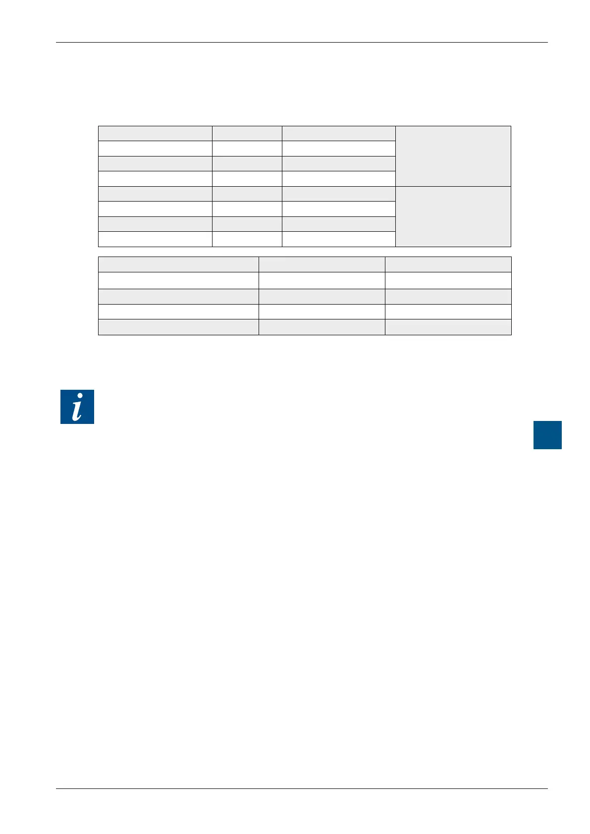
A.2.3 TTY/currentloop
SignalstoTTY/currentloop
Terminal 11 TS Transmitter Source
Transmitter
Terminal 13 TA Transmitter Anode
Terminal 16 TC Transmitter Cathode
Terminal 18 TG Transmitter Ground
Terminal 12 RS Receiver Source
Receiver
Terminal 14 RA Receiver Anode
Terminal 17 RC Receiver Cathode
Terminal 19 RG Receiver Ground
Signal type Required value Nominal value
Power for logic L (space) -20 mA to + 2 mA 0 mA
Power for logic H (mark) +12 mA to +24 mA +20 mA
Neutral voltage to TS, RS +16 V to +24 V +24 V
Short circuit power on TS, RS +18 mA to +29.6 mA +23.2 mA
The idle state of the data signals = “mark”
By wiring to the cable connector, the user selects either an “active” or “passive” cir-
cuit.
The max. transmission rate for 20 mA TTY / current loops is 9600 bps.