Saia-Burgess Controls AG
Manual Manual PCD 1 / PCD 2 Series │ Document 26 / 737 EN22 │ 2013-11-26
5
Input/output (I/O) modules
5-123
Motion control modules for servo-motors
5.19.1 PCD2.H31x, motion control module for servo-motors, 1-axis encoder
Application
The PCD2.H31x motion control module is an intelligent I/O module. The module is
used to position a single axis with variable speed control DC or AC servomotors.
This requires the drive unit to have a power stage and incremental shaft encoder for
capturing position or speed.
Each module contains a single-chip processor that independently controls every
movement according to parameters supplied by the user program (velocity,
acceleration and destination position). The axes are controlled independently of each
other, which means that no interpolation is possible to trace curved paths. On the
other hand, linking of multiple axes (point-point) in quasi-synchronous operation cane
be programmed.
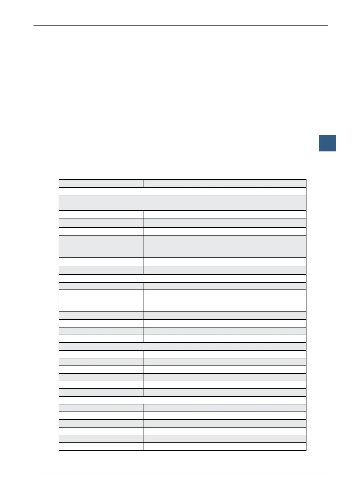
Technical data
Number of axes: 1
Motion parameters
31-bit registers are used for destination position, velocity and acceleration, numerical range
± 2
30
Position: Resolution selectable (depending on mechanical factor)
Velocity: Resolution selectable (depending on mechanical factor)
Acceleration: Resolution selectable (depending on mechanical factor)
PID controller: Sample time 341 µs, programmable proportional, integral
and differential factors. Sample time for differential part can
be programmed separately.
Analogue controller output: Velocity set point ±10 V (resolution 12 bit)
Counting frequency: max. 50 kHz
Digital inputs to PCD2.H310
Number of inputs: 1 encoder A, B, IN, 1 reference input
Nominal voltage: 24 V typically
“low” range: 0 … +4 V
“high” range: +15 … 30 V for source operation only
Input current: typically 6 mA
Circuit type: electrically connected
Reaction time: 30 µs
Encoder frequency: max. 100 kHz
Digital inputs to PCD2.H311
Number of inputs: 1 encoder A, /A, B, /B, IN, /IN, (no reference input)
Input voltage: 5 V typically
Signal level: antivalent inputs according to RS-422
Hysteresis: max. 200 mV
Line termination resistance: 150 Ω
Encoder frequency: max. 100 kHz
Analogue outputs for PCD2.H310/311
Analogue controller output: resolution 12 bit (with sign bit)
Short circuit protection: yes
Electrical isolation: no
Output voltage *): ±10 V, accuracy of adjustment ±5 mV
Circuit type: positive switching
Minimum load impedance: 3 kΩ