Saia-Burgess Controls AG
Manual Manual PCD 1 / PCD 2 Series │ Document 26 / 737 EN22 │ 2013-11-26
CPUs and expansion housings
3-24
InstallationandaddressingofPCD2I/Omodules
3
3.7 Installation and addressing of PCD2 I/O modules
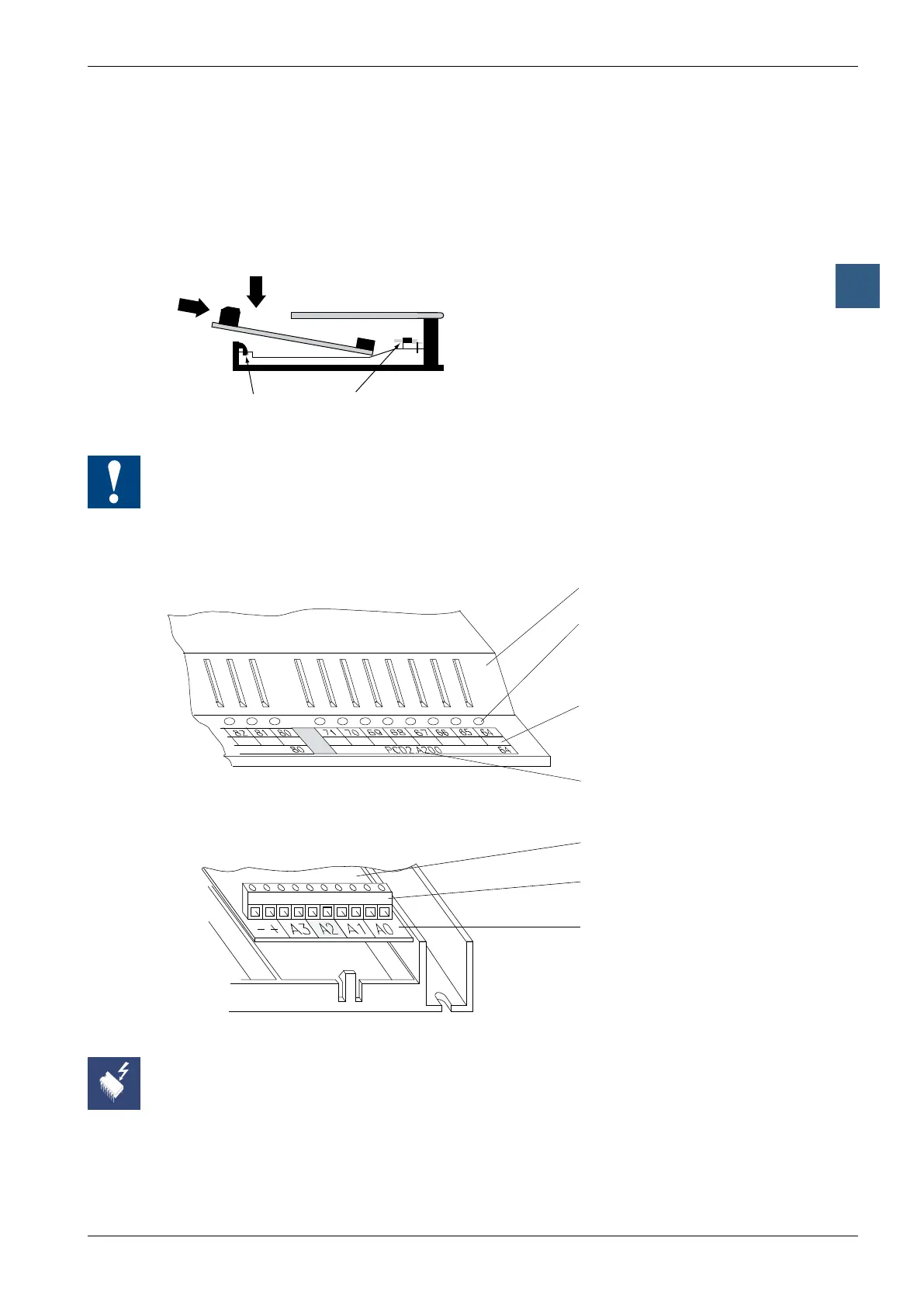
3.7.1 Insertion of I/O modules
TheI/Omoduleisinsertedfromtheside,pushedtowardsthemiddleoftheunituntilit
reaches the end stop, and snapped into the retaining catch.
Retaining catch Bus connector
I/OmodulesandI/Oterminalblocksmayonlybepluggedinandremovedwhenthe
Saia PCD
®
and the external +24 V are disconnected from the power supply.
3.7.2 Address and terminal designation
Cover of PCD2
LED display of status
I/O function name *)
I/O module name
I/O-module
Terminal numbers
Function mnemonics
and relative I/O-address
8 7 6 5 3 2 1 04
9
*) All PCD1/PCD2 units are suitably labelled
Removing the cover gives access to terminals, but also exposes components that are
sensitive to electrostatic discharges.