Saia-Burgess Controls AG
Manual Manual PCD 1 / PCD 2 Series │ Document 26 / 737 EN22 │ 2013-11-26
4
Communication interfaces
4-45
MP-Bus PCD2.T500
4.11.5 Conguration examples
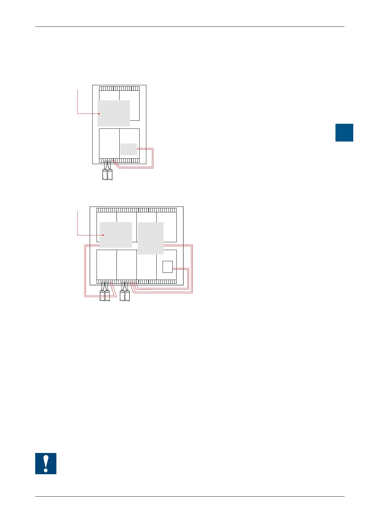
Conguration example 1 with PCD1.M1xx
PCD2.T500
BELIMO
®
RS -232
L
ONWORKS
®
PROFIBUS DP
system
PCD1.M1xx base unit
Connection module assigned 1 × RS-232
communications interface (PCD7.F120 at
space A) and 2 MP-Bus branches
Gateway to other, higher ranking net-
works
Conguration example 2 with PCD2.M170
PCD7.F5..
PCD7.F5..
PCD2.T500
BELIMO
®
PCD2.T500
RS-
232
system
PCD2.M170 base unit
Connection module A assigned 1 × RS-
232 communications interface and 2
MP-Bus branches
Connection module B assigned 2 × RS-
232 communications interfaces and 2
MP-Bus branches
Gateway to other, higher ranking net-
works
Data exchange with DDC-PLUS systems
Every connection module (PCD2.T500 or PCD7.F180) needs an RS-232 serial
port for communication with the master station! On the PCD2.T500 connection
module, this port must be wired manually from the chosen Saia PCD
®
communica-
tions interface.
The PCD2.T500 connection module has two actuator branches (channel A and
channel B) that can run both on one or two RS-232 transmission interfaces. The
RS-232 interface connection at port 1 (terminals 2 and 3) will be for the rst actuator
branch and the RS-232 interface at port 2 (terminals 0 and 1) will be for the second
actuator branch.
In projects that only have one RS-232 transmission interface within the Saia PCD
®
,
both actuator branches (max. 16 actuators) can run on it. This involves a multiplexing
process that switches between the two actuator branches. The fundamental rule ap-
plies that the more actuators are operated on one RS-232 serial transmission inter-
face, the greater the load per branch.
In multiplex operation the communications times of all actuators on both branches
must be added together to obtain the overall cycle time. See also the examples be-
low.