Page 8/70 | May 2015 | 2.0
1.2. GeoStar 250 terminal
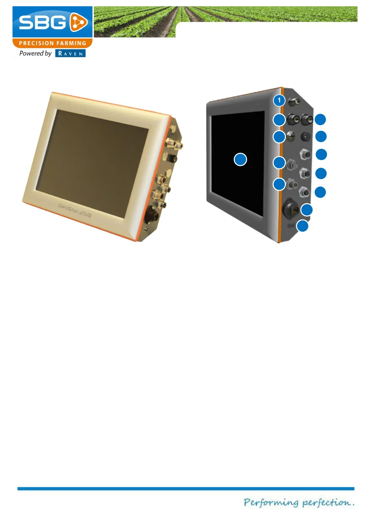
Figure 2 GeoStar 250 terminal
In Figure 2 all GeoStar 250 terminal
connections are numbered.
1. Radio (optional): coax small (TNC)
2. GPS-antenna 1: coax large (N).
Connection of the main antenna (GPS 1).
3. GPS-antenna 2: coax large (N).
Connection of the second antenna
(GPS2).
4. Main power switch
5. Screen dimmer
6. Ethernet 2 (optional): 4-pin connector.
7. RS-232: 17-pin serial connector for
external devices.
8. Ethernet: 4-pin network connector.
9. CAN-bus: 8-pin connector.
10. Extern modem: 8-pin connector for
external radio or UMTS modem.
11. Power: 4-pin connector for 12V power.
12. USB
13. Touch-screen: operations are performed
exclusively via a colour touch-screen.