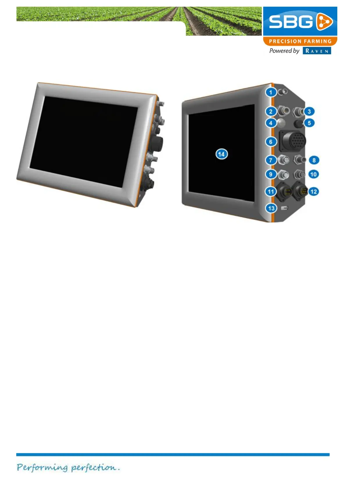
1.3. GeoStar 200-Terminal
Figure 3 GeoStar 200 terminal
In Figure 3 all GeoStar 200 terminal
connections are numbered.
1. Radio connection: coax small (TNC)
2. GPS antenna connector 1: coax large
(N). Connection of the main antenna
(GPS 1).
3. GPS antenna connector 2: coax large
(N). Connection of the second antenna
(GPS 2).
4. Main switch
5. Screen dimmer
6. Data transmission cable: 19-pin plug-
in/screw connector for the sensor box
7. Ethernet: 4-pin plug-in/screw connector
for 12V power supply.
8. CAN bus connection: 8-pin connector
9. External modem: 8-pin connector for an
external radio or UMTS modem
10. RS-232 interface: 17-pin serial plug-
in/screw connector for an external device
connection
11. Power cable: 4-pin connector for 12V
power.
12. External analogue terrain
compensation module connector: 7-pin
connector for the analogue terrain
compensation module on the implement
13. USB interface
14. Touch-screen: operations are performed
exclusively via a colour touch-screen.