Miscellaneous
OPM 250 en-GB 75
© Scania CV AB 2022, Sweden
Carry out a check and adjustment of the valve
clearances and the unit injectors one more time
after the first 500 hours of operation. After this,
adjustment according to the regular interval
takes place, which is every 2,000 operational
hours.
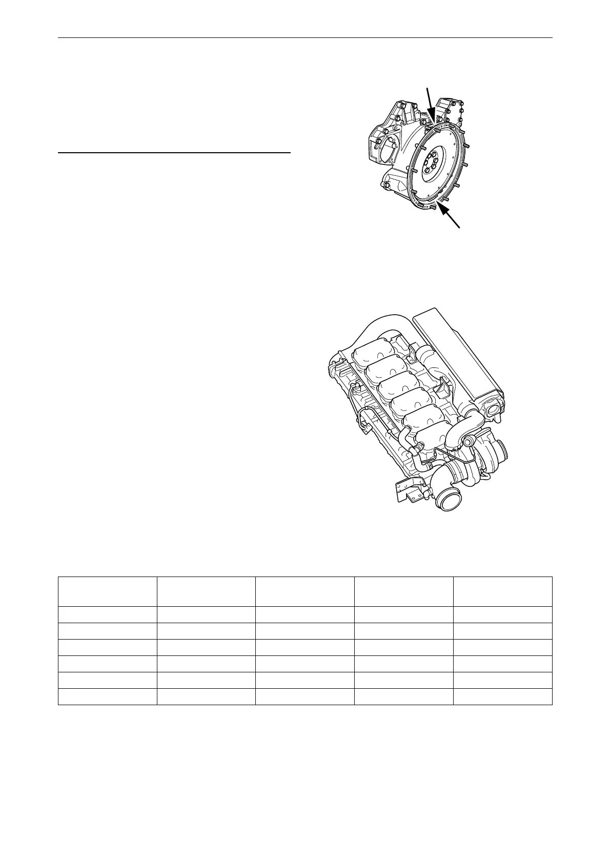
The flywheel is engraved with the reference in-
formation UP TDC, DOWN TDC and the angle
indications listed in the table below. Depending
on the engine installation, this information is vis-
ible in one of the windows, either furthest up or
furthest down on the flywheel. See illustration.
Workflow table
Adjust valves and unit injectors according to the
table below. Follow the respective column de-
pending on whether you are reading the engrav-
ing on the flywheel in the lower or the upper
window. Start adjustment at the top of the table.
Reading in the low-
er window
Valve transition on
cylinder
Adjust valves on
cylinder
Adjust injector on
cylinder
Reading in the up-
per window
DOWN TDC 1 6 2 UP TDC
120/480 5 2 4 300/660
240/600 3 4 1 60/420
DOWN TDC 6 1 5 UP TDC
120/480 2 5 3 300/660
240/600 4 3 6 60/420
310 343
Upper and lower window to read the engraving on
the flywheel.
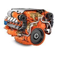
1
2
3
4
5
6
362 827
Order of cylinders.