_________________________________________________________________________________________
schunk.com XND.00005.022_A – 10/2018 36
7 Removing and replacing parts
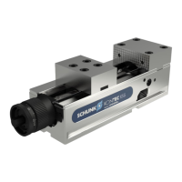
7.1 Removal
Use the clamping lever to move the hexagonal head
of the spindle to the left-hand stop and adjust the
clamping width to min. 30 mm.
Remove the knurled pin (pos. 120) from the
clamping lever and turn it into the thread of the
coupling bolt (pos. 70) through the hole in the base
plate and pull the coupling bolt out.
Note: it is also possible to remove the coupling bolt in vertical position. To do that
the fixed jaw has to be removed and the coupling bolt has to be brought into the
vertical position by turning the clamping lever by 90°. Now the bolt can be removed
using the removal tool.
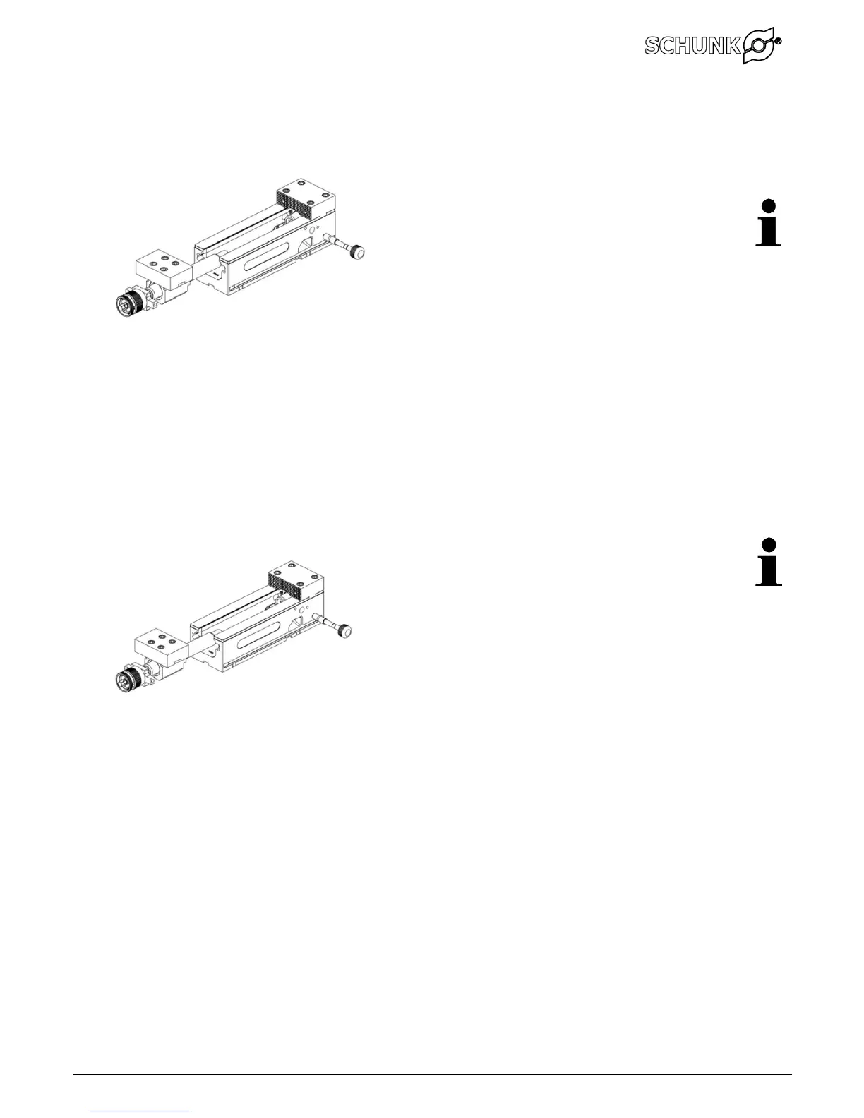
7.2 Installation
Apply sufficient lubrication during installation.
Insert the spindle assembly into the base plate.
Turn the knurled knob in order to ensure that the
holes in the mechanical force cassette and the
spindle assembly are lined up for inserting the bolt.
Use tool to insert coupling bolt in lateral hole.
Ensure you feel that the bolt has engaged.
The marking at the knurled pin (pos. 120) must be
flush with the side surface of the base plate. (this
varies according to the size of the machine)
Visual check from above.
 Loading...