Assembly
05.00 | PGN-plus-P | Assembly- and Operating Manual | en | 0389753
25
• For technical data for the suitable sensors, see assembly and
operating manual and catalog datasheet.
– The assembly and operating manual and catalog datasheet
are included in the scope of delivery for the sensors and are
available at schunk.com.
• Information on handling sensors is available at schunk.com or
from SCHUNK contact persons.
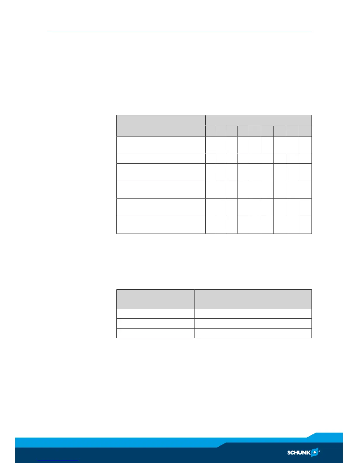
5.4.1 Overview of sensors
Designation PGN-plus-P
40 50 64 80 100 125 160 200 240
Inductive proximity switch
IN 80
– – X X X X X X X
Magnetic switch MMS 22 X X X X X X X X X
Programmable magnetic
switch MMS 22-PI1
X X X X X X X X X
Analog magnetic switch
MMS 22-A
X X X X X X X – –
Programmable magnetic
switch MMS-P 22
X X X X X X X X X
Programmable magnetic
switch MMS 22-PI2
X X X X X X X X X
5.4.2 Switch-off hysteresis
Sensors MMS 22, MMS-P 22, MMS 22-PI1 and MMS 22-PI2
The smallest detectable difference in stroke is defined in the fol-
lowing table:
The smallest detectable difference in stroke based on the nominal stroke
For grippers with X mm
nominal stroke per jaw
Min. query range per jaw/
min. queried stroke difference per jaw
X ≤ 5 mm 30% of the nominal stroke per jaw
X > 5 mm to X ≤ 10 mm 20% of the nominal stroke per jaw
X > 10 mm 10% of the nominal stroke per jaw
Example: Product with 8 mm nominal stroke per jaw
8 mm * 20% = 1.6 mm