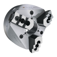
Assembly
10.00 | SWS 005 – 300 | Assembly and Operating Manual | en | 389456
23
An optional custom interface plate with a mounting hole pattern
on one side for the robot and the other for the SWK provides
adaptation between the two (consult the catalog for fastener and
locating pin specifics).
The end-effector is attached to the tool typically by using an
interface plate designed and provided by the user (The required
information is provided in the catalog for each model).
Pneumatic lines and electrical cables attached, bundled, and strain
relieved in such a manner to allow for freedom of movement
during operation.
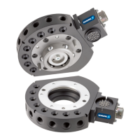
5.2 Interface Plate Design and Mounting
All interface plates must have two centering functions per
interface (dowel pin and centering flange).
The SWA to end-effector interface should utilize the diameter of
the SWA and a dowel pin for location.
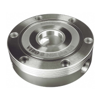
A piston cover plate is provided with the sizes SWS 005, 011, 020,
021, 040, 041, 060, 071, 150, 300 at the SWK quick-change head. If
the robot interface plate provides sealing for the piston cylinder,
then the piston cover plate is not necessary.
With the sizes SWS 007, 040Q, 046, 076, 110, 160 the piston
chamber is closed, therfore a piston cover plate is not available.
Be careful when installing the O-ring, if the O-ring is not properly
seated in the groove, it can be cut or damaged, resulting in a bad
seal and air leakage. This can cause improper and/or unsafe
operation.
The robot interface plate must be properly designed to provide
rigid mounting on the boss surfaces. The recommended
dimensions for the interface plate bore, with and without the
cover plate, are given on the respective catalog drawing for each
model.
The mating diameters must provide sufficient clearance so that
mating corner radius do not interfere.
NOTICE
Failure to follow this advice when designing the robot interface
plate may result in cover plate O-ring damage or loosening of
the interface during operation.

 Loading...