Assembly
10.00 | SWS 005 – 300 | Assembly and Operating Manual | en | 389456
37
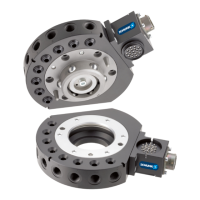
5.9.3 SWK Electrical Module Installation A15/B15 - SWS-005 and
SWS-011
M3Socket Flat
Head Cap
Screws (Long) (2x)
M3 Socket Flat
Head Cap Screws
(Short) (2x)
M3 Socket
Head Cap
Screws (2x)
SWK
(SWK-011
shown)
Elektrical Module
(SWO-A15-K shown)
Ø Remove the four M3 socket head cap screws securing the cover
to the module.
Ø Align the cover to the SWK.
Ø Apply Loctite 222® to M3 socket head cap screws.
Ø Secure the cover with two M3 socket head cap screws. Tighten
to 0.34 Nm.
Ø Apply Loctite 222® to the four M3 socket flat head cap screws.
Ø Attach the module to the cover using the two long and two
short M3 socket flat head cap screws as shown in the figure.
Tighten to 0.34 Nm.
Ø Remove all protective caps, plugs, tape, etc from the module
prior to operation.
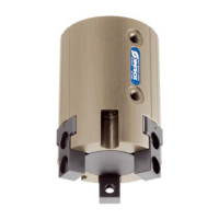
5.9.4 SWA Electrical Module Removal E10/E20 - SWS-005 and SWS-011
Connector
(2x) M3
Socket Head
Screws
(2x) Screw Locks
Elektrical Module
(SWO-A15-A shown)
SWA
(SWA-011
shown)

 Loading...