Assembly
36
10.00 | SWS 005 – 300 | Assembly and Operating Manual | en | 389456
5.9 Optional Module Installation
The optional modules are typically installed on tool changers by
SCHUNK prior to shipment. The steps below outline field
installation or removal as required. Tool Changers are compatible
with many different types of modules. Some modules will require
an adapter plate to be installed to the Tool Changer.
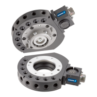
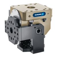
5.9.1 Electrical Module Installation E10/E20 - SWS-005 and SWS-011
SWK (SWK-011 Shown)
Electrical Module
(SWO-E10-011-K shown)
M3 Socket Head
Cap Screws (2x)
M3 Socket Head
Cap Screws (2x)
SWA
(SWA-011
shown)
Electrical Module
(SWO-E10-011-A shown)
Ø Make all soldered connections to the electrical module as
desired.
Ø Align the module to the lateral side of the SWK or SWA.
Ø Apply Loctite 222® to M3 socket head cap screws.
Ø Secure the module with two M3 socket head cap screws.
Tighten to 0,77 Nm.
Ø Remove all protective caps, plugs, tape, etc from the module
prior to operation.
5.9.2 Electrical Module Removal E10/E20 - SWS-005 and SWS-011
Ø Dock the Tool safely in the tool stand and uncouple the Tool
Changer to allow clear access to the SWK or SWA.
Ø Turn off all energized circuits (e.g. electrical, air, water, etc.)
Ø Disconnect any cables, if required.
Ø Supporting the module, remove the two M3 socket head cap
screws.
Ø Remove the module from the SWK or SWA.

 Loading...