Maintenance and Care
52
10.00 | SWS 005 – 300 | Assembly and Operating Manual | en | 389456
Ø If the proximity sensor is not functioning properly replace.
Disconnect the sensor cable and discard.
Ø Back the sensor hex nut to the cable end of the new sensor.
Ø Thread the proximity sensor into the SWK until it touches the
detection shaft, then back the sensor off 1/2 turn.
NOTICE
Operating the locking mechanism with the sensor touching the
detection shaft will damage the sensor.
• Do not operate locking mechanism with sensor touching the
detection shaft.
• Back off the sensor ½ turn and secure with the set screw
before operating the locking mechanism.
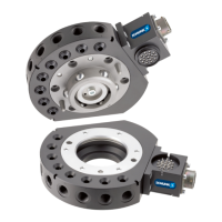
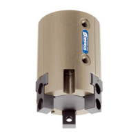
Sensor Interface Plate (SIP)
Detection Shaft
Hex Nut
Proximity Sensor
SWS-021
(SWK Shown)
(4x) M4 Socket Flat Head Cap Screws
Ø Connect the sensor cable. The proximity sensor LED should be
illuminated.
Ø Holding the sensor in position apply Loctite 222® to the
proximity sensor threads between the hex nut and the SWK.
Tighten the hex nut and torque to 0,9 Nm
Ø Attach the SWK to the adapter plate using the six M4 socket
head cap screws.Tighten to 1,1 Nm
Ø If required, connect other utilities to the optional modules on
the SWK.
Ø Confirm the operation of the replaced sensor by issuing the
Lock command to lock a SWA to the SWK and then checking to
see that the LED in the replaced Sensor body is on.
Ø After repair is complete, energize all circuits (electrical, air,
water, etc.).

 Loading...