16
© 2013 SeaStar Solutions Optimus 360 Joystick Control System, Rev. C
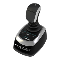
On outboard boats these are always located just below the engine
cowling and are attached to the engine tiller arm. There will be one
SmartCylinder for each engine on twin-engine boats. Most triple- and
quad-engine boats use tie-bars to steer a pair of engines with a
single SmartCylinder.
3.8 SmartCylinders
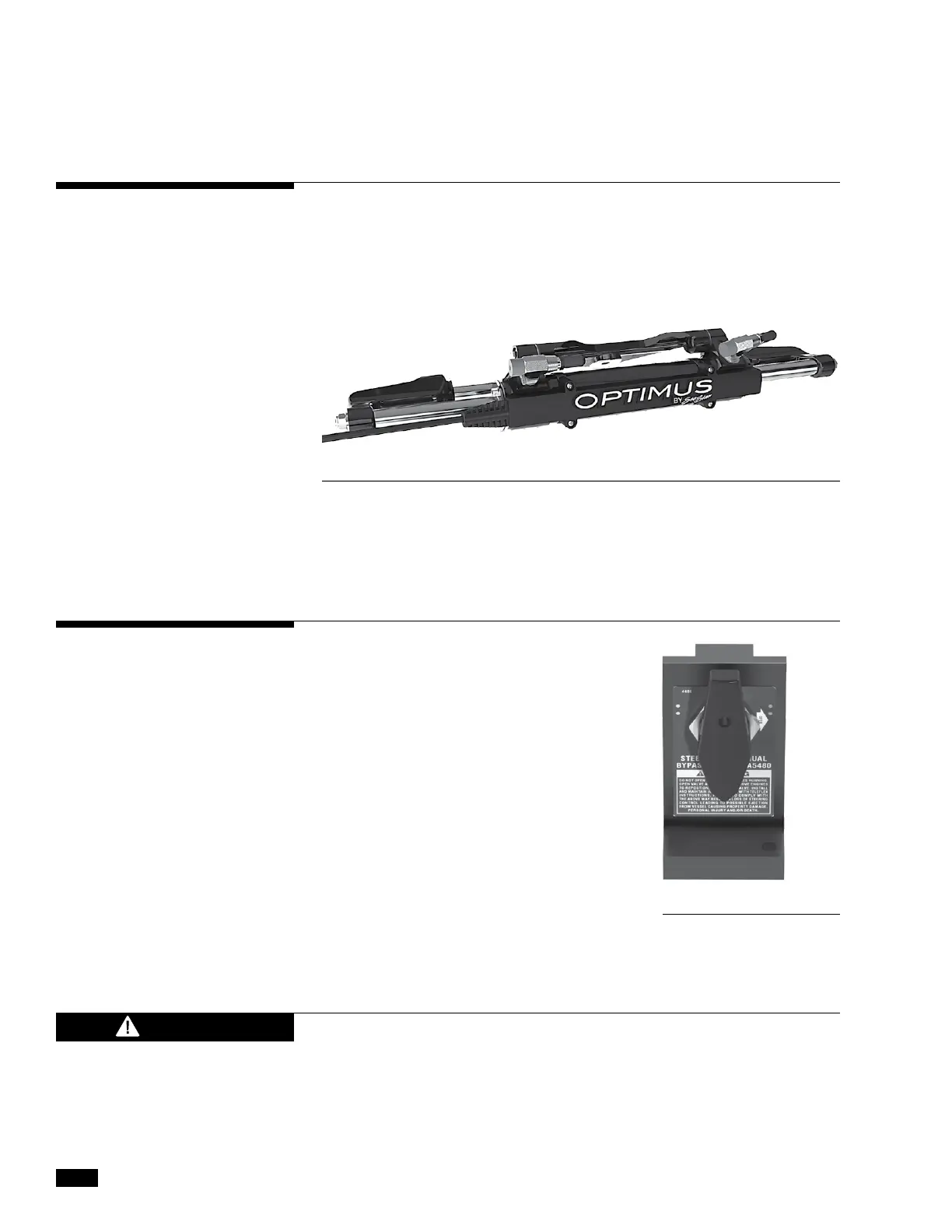
3.9 Steering Service Valves
Figure 3-7. SmartCylinder with sensor.
These are located in the hydraulic
lines that go from the steering
pumps to the SmartCylinders.
There is one for each steering
cylinder.
WEAR A COAST GUARD-APPROVED PERSONAL FLOTATION DEVICE
(PFD) WHEN MANUALLY REALIGNING ENGINES.
The steering service valves permit the
bypass of the EPS system and allow
the engines to be manually positioned.
They should only be used in the event of
an EPS system failure. Instructions on
how to proceed will be supplied on the
CANtrak display or in Section 10.2.
Figure 3-8. Steering service valve
WARNING
 Loading...

