Universal Radiographic System
Service Manual
SM-0524R4
41
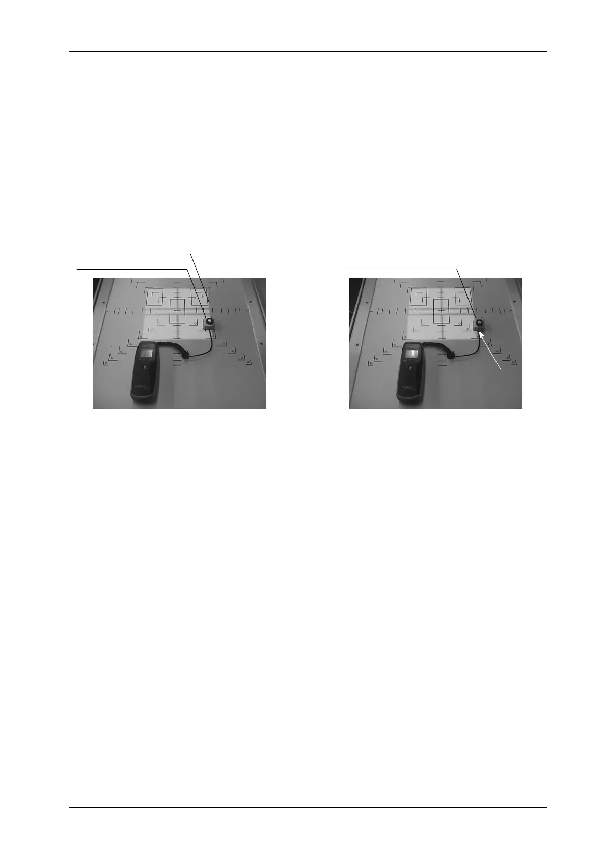
8. T urn ON the Collimator Light. Measure the maximum illumination; this
should occur near the field center. Slide the light sensor along the
Table-Top, and locate the point where the illumination drops to a 75% of
the maximum. This point is defined by BRH as lying on the edge of the
Light Field (ref er to Illustration 4-19). All subsequent measurements will
be referenced to this point and to this definition of “edge”.
Illustration 4 -19
Light Contrast Calculation
EDGE OF A QUADRANT
LIGHT SENSOR ON THE LEFT EDGE
BRH POINT
(LIGHT DROPS 25%)
LIGHT SENSOR ON THE RIGHT EDGE
9. Measure the illumination at a point 3 mm from the edge of the field toward
the center of the field (Light sensor on the left of edge). (Refer to
Illustration 4-19). Record this as I
1
.
10. Measure the illumination at a point 3 mm from the edge of the field away
from the center of the field (Light sensor on the right of edge). (Refer to
Illustration 4-19). Record this as I
2
.
11. Correct the values of I
1
and I
2
by subtracting from each value the ambient
light level measured in step-7. Now divide the corrected value of I
1
by
I
2.
This ratio should be 4 or more.
12. Repeat the process from step-8. for all quadrants of Light Field.
13. If the deviation of Light Field Contrast Ratio is out acceptance limits, it
is necessary check the following:
G Check that the Collimator Lamp, the Mirror and the Mylar window
are not dirty or discolored.
G The Light Field Intensity level shall be higher of 170 lux.
G The ambient light level shall be low as it affects the accuracy of the
measurements.