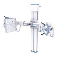
Universal Radiographic System
Service Manual
SM-0524R4
5
SECTION 3 INSTALLATION
This Section describes the Installation procedure for a system
(standard model) with the Receptor placed at the left side of the
unit when the Swivel Arm is in horizontal position. If the system
(optional model) has the Receptor placed at the right side of the
unit, position of the Control Unit (Wall Box), Bucky,
Tube-Collimator Assembly, ceiling pole and clamp to fasten the
HV Cables of the X-ray Tube should be installed in the reverse
side.
Perform Installation following the order described below.
DO NOT REMOVE SAFETY LOCKING ROD FROM THE
CENTRAL CARRIAGE UNTIL SPECIFICALLY INSTRUCTED
IN THIS DOCUMENT. (REFER TO ILLUSTRATI ON 3-3).
At least two people are required to perform next operation.
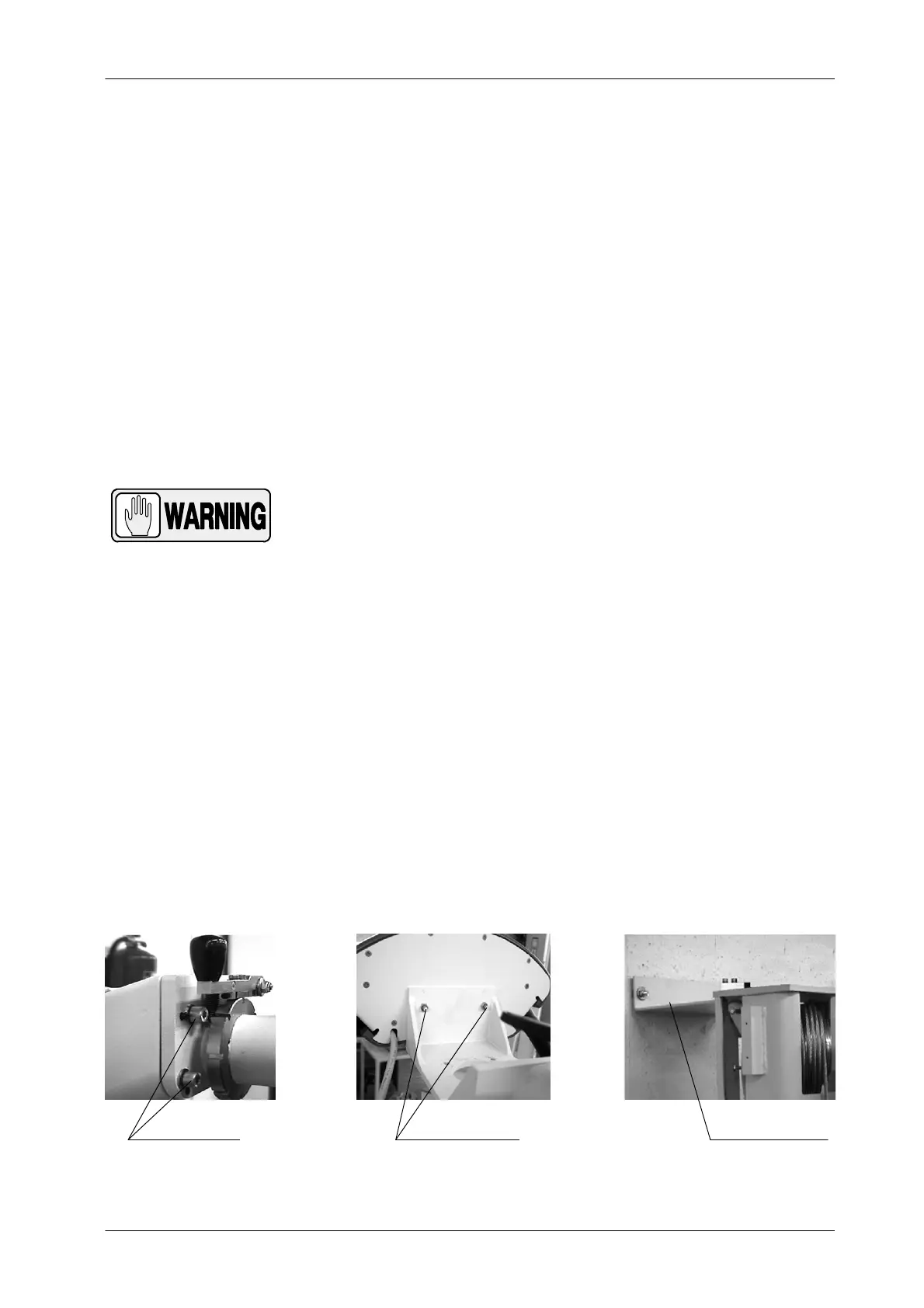
1. Assemble the Support of the T ube-Collimator to the Upper Carriage
using the four Safety Screws installed in the carriage.
2. Install the Control Panel by using the two bolts at its rear side.
3. Lift the Column as much as necessary as to mount the Upper Wall
Support in its upper part.
4. Place the Column standing-up and position it against the wall on its final
site in the room. While one person is holding up the Column, the other
one should level it vertically on both lateral sides and on the front,
marking its anchoring positions on the floor and on the wall.
Illustration 3-1
Installation of Tube-Collimator Assembly and Upper Wall Support
UPPER WALL SUPPORTSAFETY SCREWS CONTROL PANEL BOLTS
Note .
Note .