Do you have a question about the Sedecal SPL-HF 2.0 and is the answer not in the manual?
Specifies power supply voltage, impedance, and circuit breaker recommendations.
Lists necessary tools and equipment for configuration, calibration, and troubleshooting.
Details the function and settings of DIP switches on the control board.
Step-by-step guide on accessing and modifying unit configuration data.
Instructions for configuring workstation settings for detectors or bucky systems.
Procedure for setting maximum and minimum mA values for focal spots.
Guide on selecting and identifying the X-ray tube installed in the unit.
Instructions for setting the time duration for 'Prep' and collimator light features.
How to set the power percentage limit for the X-ray tube.
Configuration settings for speaker sound, time updates, and collimator light.
Procedure for setting the unit's internal date and time.
Explains how to access service functions on units with a touch screen console.
Steps to connect the oscilloscope and prepare for calibration measurements.
Overview of parameter calibration procedures including filament, kVp, and mA gain.
Procedure for initial calibration of filament current for specific mA stations.
Steps to calibrate the kVp gain using a non-invasive kVp meter.
Procedure for calibrating the mA gain before autocalibration.
Guide to performing the automatic calibration process for mA stations.
Manual calibration steps for filament current when autocalibration fails.
How to manually set or adjust kVp and mA gain values.
Procedure for aligning the X-ray beam with the cassette film and test tools.
Steps to ensure the light field accurately matches the X-ray field.
Test to verify the accuracy of the field size indicator.
General steps and guidelines for troubleshooting unit issues.
Procedure for re-initializing the EEPROM memory, often needed after board replacement.
Specific troubleshooting procedures for units equipped with a touch screen.
Interpretation of messages displayed on the touch screen console for diagnostics.
List and explanation of error codes generated by the unit for troubleshooting.
Steps to safely open the unit for accessing internal components.
Instructions for removing and replacing the upper cover of the unit.
Instructions for removing and replacing the lower cover of the unit.
Procedure for replacing the unit's handle.
Steps for replacing the support structure for the handswitch.
Guide for replacing the collimator assembly.
Instructions for removing and replacing the DAP Rails and SID Guard.
Steps for replacing the main portable control board.
Procedure for replacing the unit's real-time clock battery.
Instructions for replacing the unit's keyboard.
Steps for replacing the handswitch control board.
Procedure for replacing the snubber component.
Instructions for replacing the filaments high-frequency board.
Steps for replacing the control driver board.
Procedure for replacing the high voltage transformer assembly.
Steps to detach the X-ray power unit from the trolley arm.
Guide for replacing the collimator on the trolley unit.
Instructions for removing and replacing the DAP Rails and SID Guard on the trolley.
Steps to access components within the power unit of the trolley.
Instructions for removing and replacing the upper cover of the trolley power unit.
Instructions for removing and replacing the lower cover of the trolley power unit.
Steps for replacing the portable control board on the trolley unit.
Procedure for replacing the real-time clock battery in the trolley unit.
Instructions for replacing the keyboard on the trolley unit.
Procedure for replacing the snubber component in the trolley unit.
Instructions for replacing the filaments HF board in the trolley unit.
Steps for replacing the control driver board in the trolley unit.
Procedure for replacing the high voltage transformer in the trolley unit.
Steps to access components within the central support of the trolley.
Procedure for replacing the circuit breaker in the central support.
Instructions for replacing the EMC input filter board.
Procedure for replacing the inductance chopper.
Instructions for replacing the power supply unit.
Steps for replacing the power and communication harness.
Instructions for replacing the handswitch.
Steps to access components within the 3P console box.
Procedure for replacing the power line cable in the 3P console.
Instructions for replacing the connectors board.
Steps for replacing the remote console 3P board.
Instructions for replacing the keyboard in the 3P console.
Steps to access components within the touch screen console box.
Procedure for replacing the power line cable in the touch screen console.
Instructions for replacing the connectors board.
Steps for replacing the PC Kit including the APR base board.
Procedure for replacing the battery on the APR base board.
Instructions for replacing the touch screen display.
Guidelines and schedule for performing periodic maintenance on the unit.
Procedures for cleaning the unit's external and internal surfaces safely.
Specific instructions for cleaning the unit's exterior.
Warning and caution regarding internal cleaning procedures.
Procedure for checking electrical connections, cables, and connectors.
Tests to check the condition and functionality of the collimator.
Procedure for verifying the operation of the control panel components.
Test to verify correct operation of radiographic parameters using an oscilloscope.
Procedures for aligning the X-ray beam and testing the field size indicator.
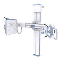
Parts list and diagrams for the monoblock unit with a portable stand.
Detailed parts breakdown and identification for the X-ray power unit.
Parts list and diagrams for the optional portable stand.
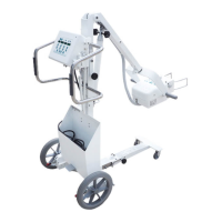
Parts list and diagrams for the monoblock unit with a trolley.
| Brand | Sedecal |
|---|---|
| Model | SPL-HF 2.0 |
| Category | Medical Equipment |
| Language | English |