Portable X-ray Units
Service Manual
SM-1076R2
142
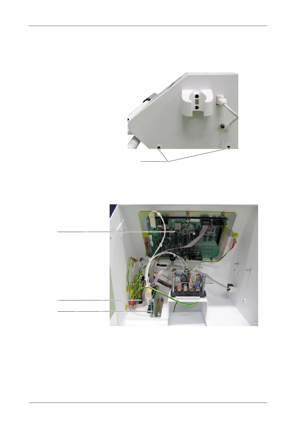
2. Remove the three remaining screws at both sides of the Console’s cover
on its lower part.
Screws (4)
3. Lift the cover up.
4. Replace the respective part in the Console Box as described in the next
sections.
Power Line Cable
Connectors Board
Remote Console 3P Board
5. Once the components in the Console Box have been replaced, assemble
the Console Box to the Trolley.
6. Connect the two cables of the Power / Communication Harness to the
Power Unit.
7. Screw the Connector Module’s cover to the Trolley.