Do you have a question about the Sedecal X and is the answer not in the manual?
Explains the meaning of DANGER, WARNING, and CAUTION symbols indicating potential hazards.
Describes various general safety symbols including documents, radiation, voltage, ground, and waste.
Details required tools for installation and essential site preparation checks.
Covers initial unpacking, component inspection, and verification steps upon receipt.
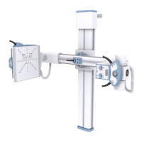
General installation description, safety warnings, and initial column setup procedures.
Steps for installing the X-ray tube, collimator, Bucky, and control unit.
Procedures for powering up the system and performing operational checks.
Lists specialized tools for adjustments and procedures for balance tests.
Adjusting safety limits for motorized movements and SID.
General procedures for aligning the X-ray beam, including light field.
Detailed procedure for aligning the light field to the X-ray field.
Detailed procedure for adjusting X-ray beam perpendicularity.
Detailed procedure for centering X-ray field and image receptor.
Procedure for testing the accuracy of the SID indicator.
Procedure for testing the accuracy of the field size indicator.
Procedure for testing collimator lamp brightness and contrast.
Guidelines for general cleaning of the unit's external and internal surfaces.
Procedures for performing essential electrical and mechanical checks.
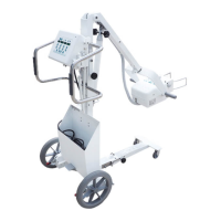
List of spare parts for the manual version of the system.
List of spare parts for the motorized version of the system.
Lists spare parts for the power box and various cables.
Visual reference for spare parts of the manual version.
Introduction to the wiring diagrams and interconnection maps.
Detailed wiring diagram for the universal interconnection.
Schematic diagram for the power supply box.
Interconnection schematic for the motorized URS.
Schematic diagram for the Optima URS motorized board.
Logic schematic for the Optima URS motorized board.
Schematic diagram for the motorized display.
Interface schematics for table, vertical, and US X-ray bucky types.
Interconnection schematic for the AEC system.
| Brand | Sedecal |
|---|---|
| Model | X |
| Category | Medical Equipment |
| Language | English |