Universal Radiographic System
Service Manual
SM-0524R4
6
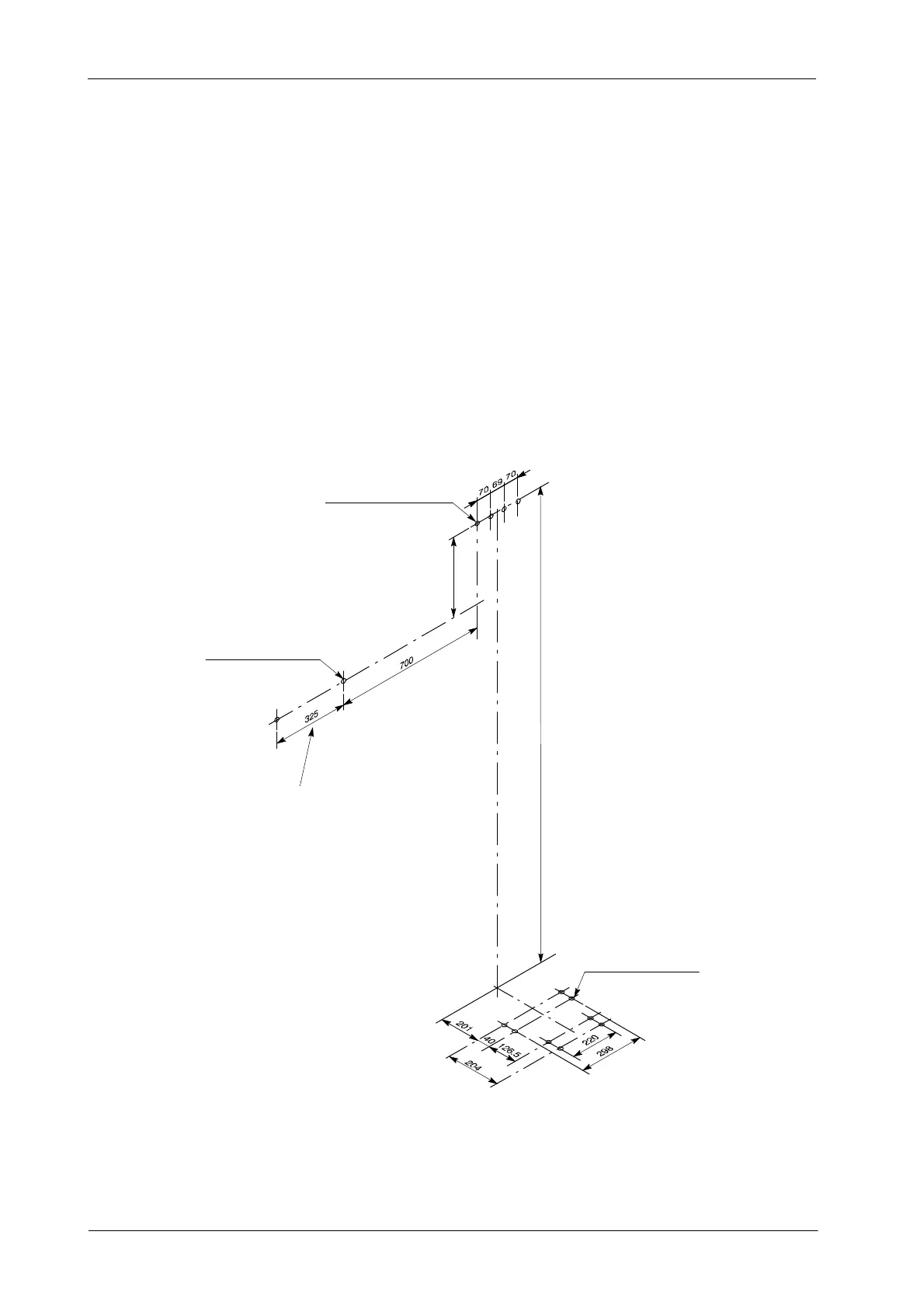
5. Move the Column and prepare the anchorages.
Distances shown on Illustration 3-2 may also be taken as
reference to mark the anchoring holes position.
Illustration 3-2
Drill Template
2163
4 wall anchoring holes
for screws diam. 8
Dimensions in mm
400
(Upper Support of the Column)
2 wall anchoring holes
for screws diam. 8
(Control Unit (Wall Box)
4 floor anchoring holes
for screws diam. 8
(Base of the Column)
If the Receptor is pl aced at the right side of the Unit,
the Control Unit must anchored at the right side of the Column
Note .