6.3 Controller Specifications
Design
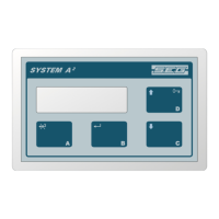
Frontpanel: Stainless steel frame with integrated keypad.
Protection: Splashproof NEMA 4 / IP65.
Rear cover: Aluminum-zink metal.
Protection: IP55.
Field enclosures: Stainless steel SIS2333.
Protection: NEMA 4 / IP65.
Cable entry: 4 x dia.19 holes w. PG11 metal glands,
1 x dia. 22,5 hole.
Display & control
Display: LCD 2x16 character, 5,5mm w. backlight.
Control: 4-key local keypad or via RS485 com port.
Memory: Lithium battery CR2450 (24x8/550mAh) back-up + Non-volatile FLASH memory.
Set-up: Interactive software via local keypad.
Power supply
Standard: 24Vdc, approx. 5W.
Protection: Fuse (internal).
Optional: External 90-250VAC / 24VDC (PW-24).
Connection
Terminal strip: 12 x 2,5 mm2 max (AWG 16) for stranded wire (Terminals: 1-6, V+,V-).
11 x 1,5 mm2 max (AWG 18) for stranded wire. (Terminals: 21-52).
Input
Load Cell: 4- or 6-wire system with sense inputs, 0,3 - 45,0mVdc.
Speed sensor: - S-E-G type F.
- Relay dry contact.
- NPN proximity switch, (13-24vdc depending on controller supply voltage.)
Max. 500Hz.
Output
Load Cell, Exc.: 12Vdc nominal.
Max. load: 140 mA (~85 Ohms).
Min. load: 1000 Ohms.
Relays (2): Dry contact N.O. 24Vdc / 1A. Relay no.1: Totaliser pulse, 100ms
Relay no.2: Selectable between Flow level, Speed level etc.
Speed sensor: 13-24Vdc, max. 50mA.
18-08-16 S44-H15E 6-7
S-E-G SYSTEM A2-H15 INSTRUCTION