2.2 Operating Concept for the WIC1
Network Cable
RJ45
RESET
WIC1
WIC1_Z04
Smart view
DiggiMEC
USB Cable
RJ45
(Rear Side)
Ready
Shortcuts
Device Data
Smart view
Operation
Device planning
Device Para
1,0
Field Para
50/60
Protection Para
7
6
5
WIC1
Operation
Device planning
Device Para
Field Para
Protection Para
Service
File Device Edit View Settings Tools Window Help
- . - - . -
- . - - . -
- . - - . -
- . - - . -
Name Value
- . - - . -
- . - - . -
- . - - . -
- . - - . -
- . -
- . - - . -
- . - - . -
Name
- . -
- . - - . -
- . -
- . -
- . -
- . - - . - - . - - . -
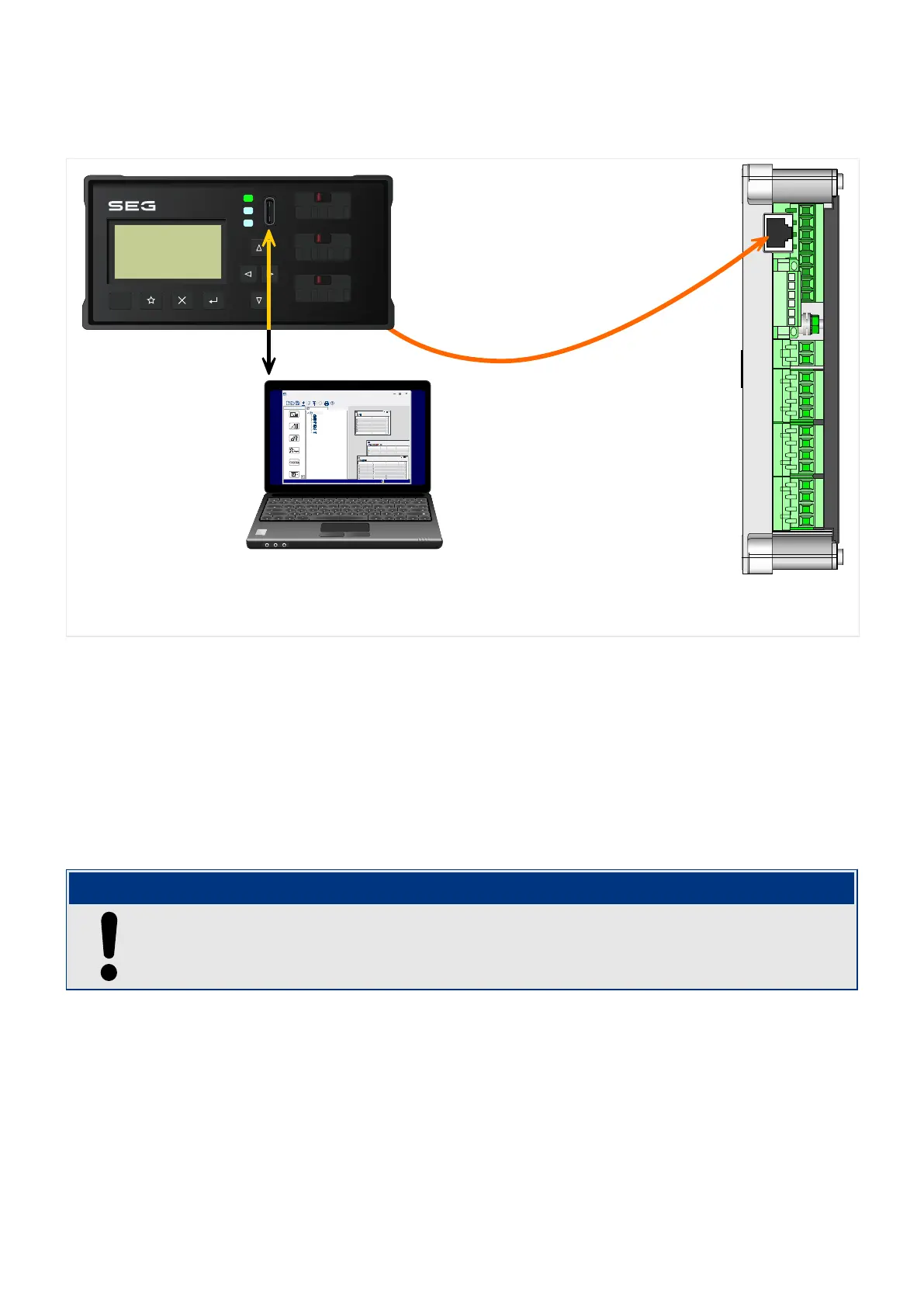
Fig. 3: Connection possibilities of a WIC1 with a DiggiMEC and a PC.
As a combination of a compact protection relay and related core-type transformer, the WIC1
has been developed especially for compact MV switchboards with circuit breakers.
The intuitive operating concept with plausibility checks and easy commissioning functions
allows a safe and time-optimized maintenance and commissioning. The WIC1 can be
(optionally) connected to the interface device DiggiMEC, which adds an LCD display, keys
and some ag indicators with output relays.
The DiggiMEC can be connected to a Windows PC, so that the parameter setting and
evaluation software Smart view can be used to congure the WIC1 and to retrieve
measurement values and fault data from the WIC1. (See also ╚═▷ “2.7.1 Smart view”.)
NOTICE!
The
DiggiMEC is always usable only with a connected WIC1 (independent of whether
there is any supply via the USB interface of the DiggiMEC).
21WIC1WIC1-1.0-EN-MAN
2 WIC1 – Introduction and General Information
2.2 Operating Concept for the WIC1
 Loading...