7.1.4.2 Wiring Checks
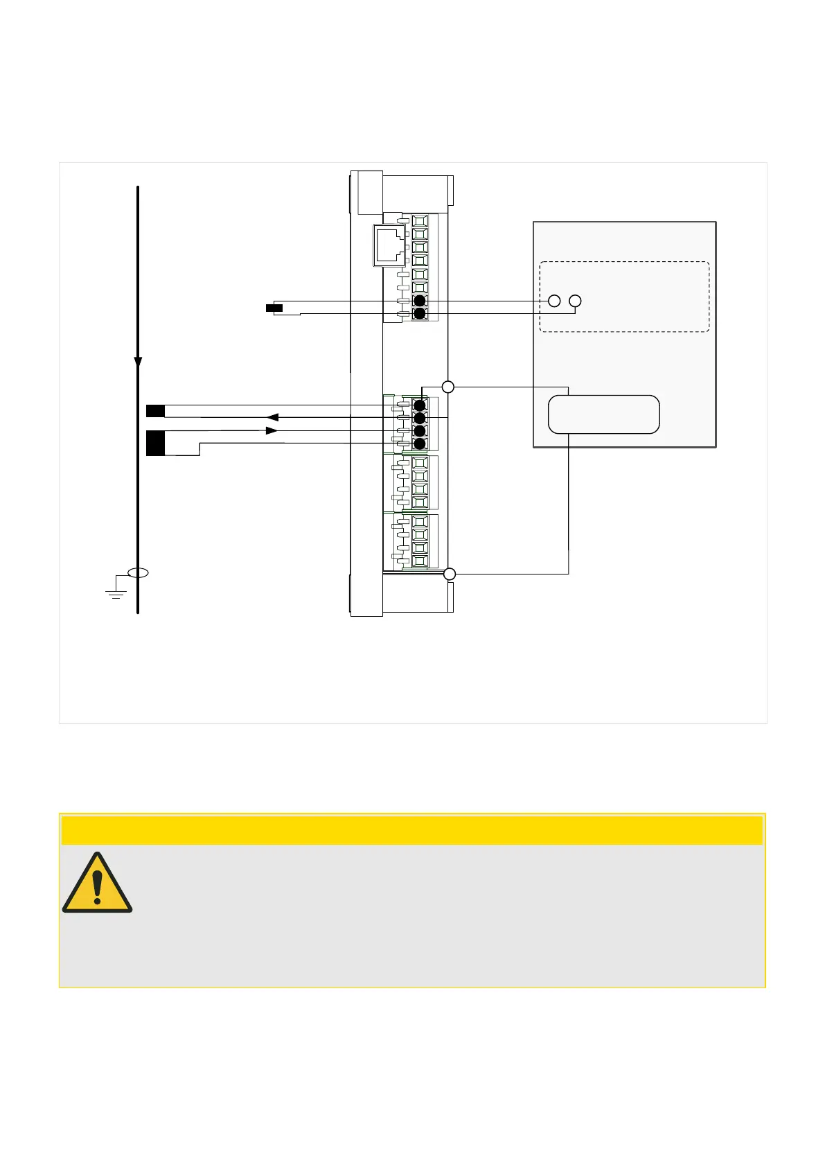
Wiring has to be checked with the circuitry shown in the diagram below.
WIC1
WIC1_Z30
S1
S2
C
D
L1
digital input
N
1 A
1-phase∿
Testing Device
X1
TC+
TC−
L1
Meas. Winding
Test Winding
trip coil
50 A
1 A
0.26 A
Fig. 69: Connection of a single-phase testing device for the example of phase L1 with CT type
WIC1W2AS1.
The testing current is fed via sockets L1, L2, L3 and N. The test winding is rated such that the
fed current of 1 A balances a primary current of 50 A (for an example CT type W2 : 16 A ...
56 AAS1).
CAUTION!
It is not allowed to connect any active voltage to the trip coil output or to the output
(ag
indicator / relay output).
The two outputs may be connected at the same time to test equipment (e. g. to binary
inputs of an Omicron
©
device) only if these two binary inputs do not share a common
potential. Otherwise this external potential bridge, together with device-internal circuits,
can produce incorrect test results.
192 WIC1 WIC1-1.0-EN-MAN
7 Commissioning
7.1.4.2 Wiring Checks
 Loading...