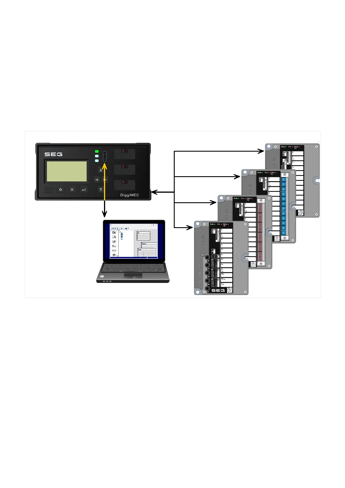
2.7 Settings – Operation
Pursuant to the intended maintenance-free design there is no user interface with display.
For the variants WIC1‑1 and WIC1‑4, all settings can only be done via the communication
interface, by means of the DiggiMEC interface device.
For the variants WIC1‑2, all settings can be made either with DIP switches, or – more
exactly – with the DiggiMEC user interface.
For the variants WIC1‑3, all settings can be made either with HEX switches, or – more
exactly – with the DiggiMEC user interface.
Ready
Shortcuts
Device Data
Smart view
Operation
Device planning
Device Para
1,0
Field Para
50/60
Protection Para
7
6
5
WIC1
Operation
Device planning
Device Para
Field Para
Protection Para
Service
File Device Edit View Settings Tools Window Help
- . - - . -
- . - - . -
- . - - . -
- . - - . -
Name Value
- . - - . -
- . - - . -
- . - - . -
- . - - . -
- . -
- . - - . -
- . - - . -
Name
- . -
- . - - . -
- . -
- . -
- . -
- . - - . - - . - - . -
RJ45
(Rear Side)
WIC1_Z05
Network Cable
RJ45
RJ45
RJ45
RJ45
WIC1-1 or WIC1-2 or WIC1-3 or WIC1-4
RESET
Smart view
USB Cable
Ready Error Pic k up
Trip
IG
IL1
IL2
IL3
N
1
2
X4X5
X6
1
2
3
4
5
6
7
8
FI+
FI−
T C+
T C−
DiggiMEC
1
3
4
5
6
2
HF
GND
T-
N
P
T+
RS485
1
1
1
C
D
1S1
C
D
1S2
2S1
2S2
1S1
1S2
C
D
1S1
C
D
1S2
2S1
2S2
1S1
1S2
C
D
1S1
C
D
1S2
2S1
2S2
1S1
1S2
X3
IL3
X2
IL2
X1
IL1
X0
IG
I
n
I
I>
t
l>
I>>
t
I>>
IG>
t
IG>
IG
IH2
%
l
peak>
IH2
max
PE X7
Ethe r net
C
4
B
3
A
2
9
1
0
8
F
7
E
6
D
5
C
4
B
3
A
2
9
1
0
8
F
7
E
6
D
5
C
4
B
3
A
2
9
1
0
8
F
7
E
6
D
5
C
4
B
3
A
2
9
1
0
8
F
7
E
6
D
5
C
4
B
3
A
2
9
1
0
8
F
7
E
6
D
5
C
4
B
3
A
2
9
1
0
8
F
7
E
6
D
5
C
4
B
3
A
2
9
1
0
8
F
7
E
6
D
5
C
4
B
3
A
2
9
1
0
8
F
7
E
6
D
5
C
4
B
3
A
2
9
1
0
8
F
7
E
6
D
5
C
4
B
3
A
2
9
1
0
8
F
7
E
6
D
5
C
4
B
3
A
2
9
1
0
8
F
7
E
6
D
5
C
4
B
3
A
2
9
1
0
8
F
7
E
6
D
5
ON DIP
1 2 3 4 5 6 7 8
ON DIP
1 2 3 4 5 6 7 8
ON DIP
1 2 3 4 5 6 7 8
ON DIP
1 2 3 4 5 6 7 8
ON DIP
1 2 3 4 5 6 7 8
ON DIP
1 2 3 4 5 6 7 8
Validity of the DIP-/HEX-Switches
Many parameters and protection functions are not accessible by the DIP switches of the
WIC1‑2 or HEX switches of the WIC1‑3. This is a natural result of the limited number
of switches.
All these settings have appropriate default values, and inaccessible protection functions are
deactivated. This way there is a well-dened functional range for the WIC1, so that it can
be used only based on DIP/HEX settings, and vice versa, the DOP/HEX switches reect the
functionality in use suciently well.
Using the DiggiMEC / Smart view, however, the whole implemented functional range with
all settings can be accessed. But if this “software-settings” operation mode is active, all
DIP/HEX settings are ignored.
• This parameter denes for the WIC1‑2 or WIC1‑3 which settings shall be used:•
• [Device planning / WIC1 + DiggiMEC] »Prot . Settings valid« =•
Options:
◦
“Switches” — DIP/HEX settings shall be used.
◦
40 WIC1 WIC1-1.0-EN-MAN
2 WIC1 – Introduction and General Information
2.7 Settings – Operation
 Loading...