3.8 Input, Output and LED Settings
3.8.1
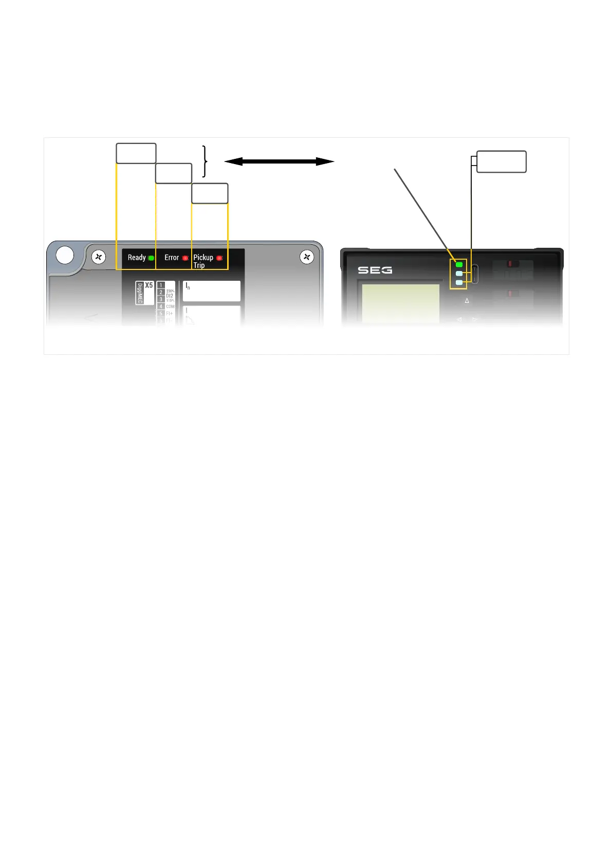
LEDs
LED
System
LED
LED
Pickup/
Trip
1
2
3
System (Ready/Error) LED
LED 2
LED 3
Ready Error Pic k up
Trip
IG
IL1
IL2
IL3
N
1
2
X4X5
X6
1
2
3
4
5
6
7
8
FI+
FI−
T C+
T C−
DiggiMEC
1
3
4
5
6
2
HF
GND
T-
N
P
T+
RS485
1
1
1
C
D
1S1
C
D
1S2
2S1
2S2
1S1
1S2
C
D
1S1
C
D
1S2
2S1
2S2
1S1
1S2
C
D
1S1
C
D
1S2
2S1
2S2
1S1
1S2
X3
IL3
X2
IL2
X1
IL1
X0
IG
I
n
I
I>
t
l>
I>>
t
I>>
IG>
t
IG>
IG
IH2
%
l
peak>
IH2
max
PE X7
Ethe r net
WI_Z0D
(* Configurable)
*
Ready
System
Error
WIC1 LEDs
The WIC1 features one green LED and two red LEDs.
• The green and the rst red LEDs are the »System« LEDs and have xed functionality•
i.e. cannot be congured. See ╚═▷ “The »System« LED(s) – “Ready”, “Error””.
•
The second red LED, labeled “Pickup / Trip”, indicates a (General) Pickup by blinking,
•
and a (General) Trip by shining constantly red. It cannot be congured. (See also ╚═▷
“4.1.1 General Pickup, General Alarm, General Trip”.)
(Of course, in case of a CT-powered WIC1, any LED can be lit only until the breaker
has interrupted the power supply.)
DiggiMEC LEDs
The DiggiMEC features three two-colored (red/green) LEDs. As long as the DiggiMEC is
connected to the WIC1 there is the following functionality:
• The rst LED corresponds to the two »System« LEDs (i. e. the LEDs “Ready” and•
“Error”) of the WIC1. See ╚═▷ “The »System« LED(s) – “Ready”, “Error””.
• The second and third LED can be congured by the user. (See ╚═▷ “3.8.1.2 LED•
Conguration (DiggiMEC)”.)
The »System« LED(s) – “Ready”, “Error”
After booting is complete and all the protection functions are »activated« and there is
enough energy for issuing a trip impulse signal, the green »System/Ready« LED lights up.
93WIC1WIC1-1.0-EN-MAN
3 Hardware
3.8 Input, Output and LED Settings
 Loading...