Schweitzer Engineering Laboratories, Inc. SEL-487E-3, -4 Data Sheet
7
Synchronism Check
Synchronism-check elements prevent circuit breakers
from closing if the corresponding phases across the open
circuit breaker are excessively out of phase, magnitude,
or frequency. The SEL-487E synchronism-check ele-
ments selectively close circuit breaker poles under the
following criteria:
➤ The systems on both sides of the open circuit
breaker are in phase (within a settable voltage
angle difference).
➤ The voltages on both sides of the open circuit
breaker are healthy (within a settable voltage
magnitude window).
The synchronism-check function is available for as many
as six breakers with a user-selectable reference voltage.
Each element has a user-selectable synchronizing voltage
source and incorporates slip frequency, two levels of
maximum angle difference, and breaker close time into
the closing decision. Include the synchronism-check ele-
ment outputs in the close SEL
OGIC control equations to
program the relay to supervise circuit breaker closing.
Current Unbalance Elements
The current unbalance logic uses the average terminal cur-
rent to calculate the percentage difference between the
individual phase current and the terminal median current.
If the percentage difference is greater than the pickup value
setting, the phase unbalance element is asserted. To pre-
vent this element from asserting during fault conditions
and after a terminal circuit breaker has closed, the final
terminal unbalance output is supervised using current,
fault detectors, and the open-phase detection logic.
Fault Identification Logic
The purpose of the fault identification logic is to deter-
mine, on a per-terminal basis, which phase(s) was involved
in a fault for which the transformer tripped. Determining
the faulted phase is based on current inputs from wye-
connected CTs. The logic does not determine the faulted
phase for the following cases:
➤ Delta-connected CTs (CTCONm = D)
➤ Where only zero-sequence current flows through
the relay terminal (no negative-sequence current
and no positive-sequence current)
This logic identifies a sector in which a faulted phase(s)
can appear by comparing the angle between the negative-
and zero-sequence currents I2m and I0m (m = S, T, U, W,
X, Y).
Applications
The SEL-487E offers comprehensive transformer protec-
tion features. Around the clock winding phase compen-
sation simplifies setting the transformer protection elements.
Harmonic restraint and blocking by using second- and
fourth-harmonic quantities provide secure operation during
transformer energization, while maintaining sensitivity
for internal faults. Waveshape-based inrush detection
addresses inrush conditions that contain low second- and
fourth-harmonic content. For applications without voltage
inputs (therefore no V/Hz element), use the fifth-harmonic
monitoring to detect and alarm on overexcitation conditions.
Flexible ordering options allow either 1 A or 5 A CT inputs
for each transformer winding to configure the SEL-487E
for a variety of CT configurations.
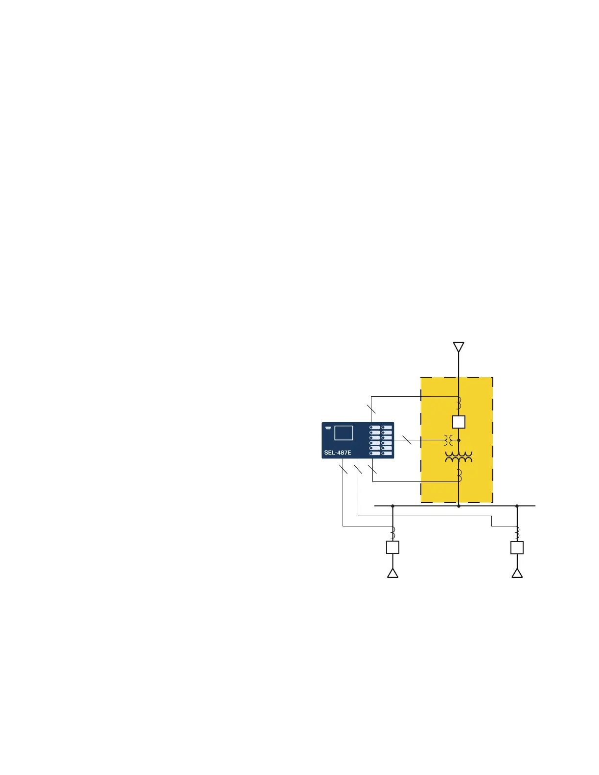
Configure the SEL-487E for transformer differential pro-
tection for transformer applications by using as many as
six three-phase restraint current inputs. This includes sin-
gle transformers with tertiary windings. Figure 5 shows
the SEL-487E in a typical two-winding transformer
application. Use the remaining three-phase current inputs
for feeder backup protection.
Use the negative-sequence differential element for sensitive
detection of interturn faults within the transformer winding.
Phase-, negative-, and zero-sequence overcurrent elements
provide backup protection. Use breaker-failure protec-
tion with subsidence detection to detect breaker failure
and minimize system coordination times.
When voltage inputs are provided to the SEL-487E, voltage-
based protection elements and frequency tracking are
made available. Frequency tracking from 40.0 to 65.0 Hz
Figure 5 Two-Winding Transformer Application
Transformer
Differential Zone
3
3
333