Schweitzer Engineering Laboratories, Inc. SEL-487E-3, -4 Data Sheet
9
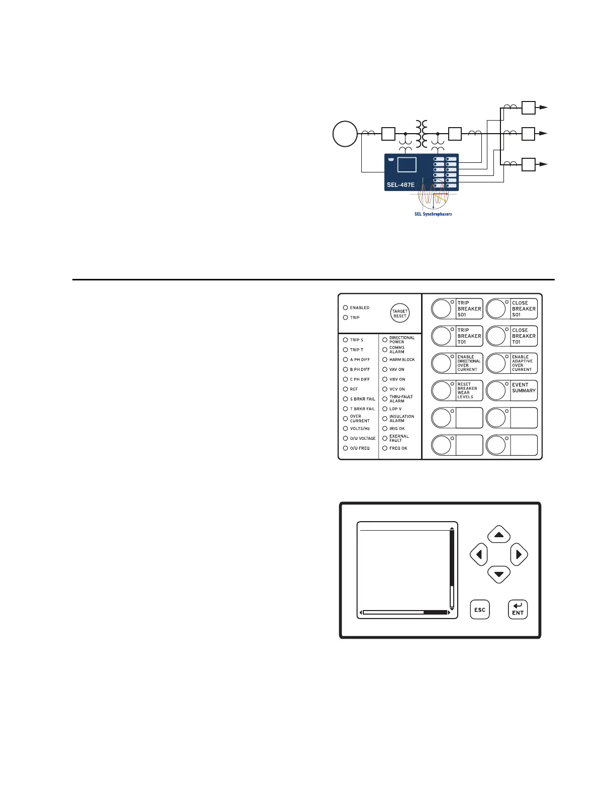
Synchrophasor Applications
Use the SEL-487E as a station-wide synchrophasor mea-
surement and recording device. The SEL-487E provides
as many as 24 analog channels of synchrophasor data and
can serve as a central phasor measurement unit in any sub-
station or power generation facility. The SEL-487E can be
configured to send five unique synchrophasor data streams
over serial and Ethernet ports. Measure voltage and cur-
rent phase angle relationships at generators and trans-
formers, key source nodes for stability studies and load
angle measurements. Use the SEL-487E to store as much
as 120 seconds of IEEE C37.118 binary synchrophasor
data for all 24 analog channels at a recording rate of 60
messages per second. A SEL
OGIC control equation trig-
gers storage of data. Capture data as necessary, and then
store this information in SEL-487E nonvolatile memory.
Use this capability to record system transients for com-
parison to state machine estimations.
Additional Features
Front-Panel Display
The LCD shows event, metering, setting, and relay self-
test status information. The target LEDs display relay
target information as shown in Figure 12.
The LCD is controlled by the navigation pushbuttons
(Figure 13), automatic messages the relay generates, and
user-programmed analog and digital display points. The
rotating display scrolls through alarm points, display points,
and metering screens. If none are active, the relay scrolls
through displays of the fundamental and rms metering
screens. Each display remains for a user-programmed
time (1–15 s) before the display continues scrolling. Any
message the relay generates because of an alarm condition
takes precedence over the rotating display.
Figure 12 and Figure 13 show close-up views of the front
panel of the SEL-487E. The front panel includes a 128 x
128 pixel, 3" x 3" LCD screen; LED target indicators; and
pushbuttons with indicating LEDs for local control func-
tions. The asserted and deasserted colors for the LEDs
are programmable. Configure any of the direct-acting push-
buttons to navigate directly to any HMI menu item for fast
viewing of events, alarm points, display points, or the SER.
Bay Control
The SEL-487E provides dynamic bay one-line diagrams on
the front-panel screen with disconnect and breaker con-
trol capabilities for user-selectable bay types. You can
Figure 11 Station-Wide Synchrophasor Application
Figure 12 Factory-Default Status and Trip Target LEDs
(12 Pushbutton, 24 Target LED Option)
Figure 13 Factory-Default Front-Panel Display and
Pushbuttons
FAULT QUANTITIES
(pu)
Zone 1 Zone 2
IOPA= 4.35 0.20
IOPB= 4.76 0.12
IOPC= 0.56 0.88
IRTA= 6.65 1.09
IRTB= 6.21 1.81
IRTC= 1.06 1.25
EVENT SUMMARY 10002