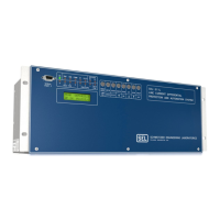
SEL-487E-3, -4 Data Sheet Schweitzer Engineering Laboratories, Inc.
10
download the QuickSet interface from selinc.com to
obtain additional user-selectable bay types. The bay con-
trol can control as many as ten disconnects and two break-
ers, depending on the one-line diagram selected. Certain
one-line diagrams provide status for as many as three
breakers and five disconnect switches. Operate discon-
nects and breakers with ASCII commands, SEL
OGIC
control equations, Fast Operate Messages, and from the
one-line diagram. The one-line diagram includes user-
configurable apparatus labels and as many as six user-
definable analog quantities.
One-Line Bay Diagrams
The SEL-487E offers a variety of preconfigured one-line
diagrams for common bus configurations. Once you
select a one-line diagram, you can customize the names
for all of the breakers, disconnect switches, and buses.
Most one-line diagrams contain analog display points.
You can set these display points to any of the available
analog quantities (including remote 87L currents) with
labels, units, and scaling. The SEL-487E updates these
values along with the breakers and switch position in real
time to give instant status and complete control of a bay.
The following diagrams demonstrate some of the precon-
figured bay arrangements available in the SEL-487E.
Programmable interlocks help prevent operators from
incorrectly opening or closing switches or breakers. The
SEL-487E not only prevents operators from making an
incorrect control decision, but it can notify and/or alarm
upon initiation of an incorrect operation.
Circuit Breaker Operations From the
Front Panel
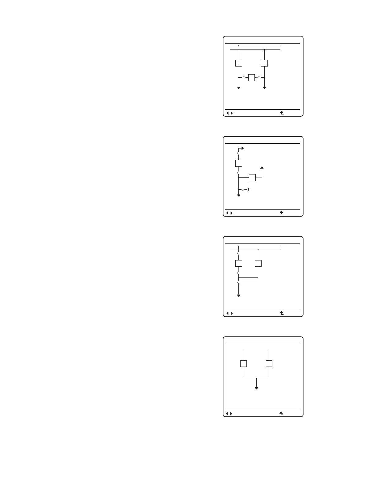
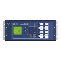
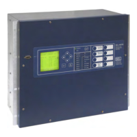
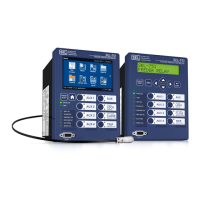
Figure 14–Figure 17 are examples of some of the select-
able one-line diagrams in the SEL-487E. Select the one-
line diagram from the Bay settings. Additional settings
for defining labels and analog quantities are also found in
the Bay settings. One-line diagrams are composed of the
following:
➤ Bay names and bay labels
➤ Busbar and busbar labels
➤ Breaker and breaker labels
➤ Disconnect switches and disconnect switch labels
➤ Analog display points
Figure 18 shows the breaker control screens available
when the ENT pushbutton is pressed with the circuit
breaker highlighted as shown in Figure 18(a).
Figure 14 Breaker-and-a-Half
Figure 15 Ring Bus With Ground Switch
Figure 16 Double Bus/Double Breaker
Figure 17 Source Transfer Bus
BAYNAME
BK2
BK1
SW1
SW2
BK3
BAYLAB2BAYLAB1
BUSNAM1
BUSNAM2
ESCNAVIG
BAYNAME
6 ANALOGS
I:99999.9 A
V:99999.9 KV
P:99999.9 MW
Q:99999.9 MV
F:99.9 HZ
BAYLAB1
SW2
SW3
BK1
BK2
SW1
BAYLAB2
ESCNAVIG
BAYNAME
6 ANALOGS
I:99999.9 A
V:99999.9 KV
P:99999.9 MW
Q:99999.9 MV
F:99.9 HZ
BUSNAM1
SW2
SW3
BK1
BK2
SW1
BUSNAM2
ESCNAVIG
BAYNAME
BUSNAM1
BK1
BK2
BUSNAM2
BAYLAB1
I:99999.9 A
V:99999.9 KV
P:99999.9 MW
I:99999.9 A
V:99999.9 KV
P:99999.9 MW
ESCNAVIG


 To Next Page